Page 43
FIGURE 43
EXHAUST
VENT
INTAKE VENT
5−1/2
(140)
Front View
12
(305)
5
(127)
18 MAX.
(457)
EXHAUST VENT
INTAKE
VENT
Side View
OPTIONAL VENT TERMINATION FOR
MULTIPLE UNIT INSTALLATION
WALL TERMINATION KIT WTK
Inches (mm)
FIGURE 44
12 MIN.
(305)
Above Grade
COVER EXHAUST
VENT WITH
1/2 (13)
FOAM
INSULATION
Front View
Side View
VENT TERMINATIONS
MODEL WTK WALL TERMINATION KIT (30G28)
EXTENDED VENT FOR GRADE CLEARANCE
Inches (mm)
5
(127)
5-1/2
(140)
EXHAUST
AIR
INTAKE
AIR
GRADE
12
(305)
8 (203)
Minimum
12 (305)
Minimum
ABOVE GRADE
INTAKE
AIR
EXHAUST
AIR
GRADE
Inches (mm)
FIGURE 45
VENT TERMINATIONS
MODEL WTKX (30G79)
EXTENSION RISER FOR GRADE CLEARANCE
4
(102)
8 MIN.
(203)
EXHAUST VENT
INTAKE
VENT
GRADE
GRADE
EXHAUST
VENT
INTAKE
VENT
34
(864)
12
(305)
9
(229)
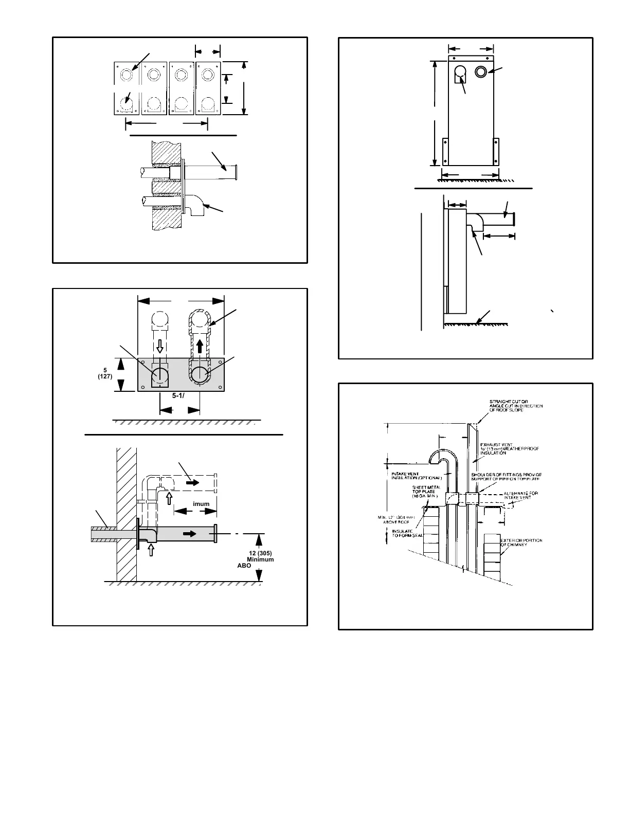
NOTE−Enclosed exhaust
pipe is insulated with 1/2"
(13mm) foam insulation.
If intake and exhaust
pipes are reversed, slit
and remove foam insula-
tion and reapply to other
vent. Exhaust vent must
be insulated.
Front View
Side View
OUTSIDE WALL
Inches (mm)
G32V VENTING IN EXISTING CHIMNEY
NOTE−Do not discharge exhaust gases directly into any chimney or vent stack. If verti-
cal discharge through an existing unused chimney or stack is required, insert piping
inside chimney until the pipe open end is above top of chimney and terminate as illus-
trated. In any exterior portion of chimney, the exhaust vent must be insulated. An alter-
nate method is to fill the chimney with vermiculite or equal to take advantage of its
acoustic and thermal properties.
FIGURE 46
8" − 12"
(203mm − 305mm)
3" − 8"
(76mm−
203mm)
3" − 8"
(76mm−
203mm)
 Loading...


