Page 6
TABLE 6
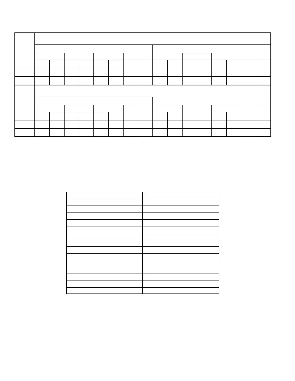
G32V5−100/125−5 Units BLOWER MOTOR PERFORMANCE
0.0" to 0.8" w.g. (0 through 200 Pa) External Static Pressure Range
Blower Speed Adjustment Settings (Switches 5 and 6)
Cool
Adjust"
Low Speed High Speed
e
ng
1
2
3 4 1
2
3 4
cfm L/s cfm L/s cfm L/s cfm L/s cfm L/s cfm L/s cfm L/s cfm L/s
Norm 1140 540 1250 590 1440 680 1550 730 1620 765 1820 860 2000 945 2100 990
–
970 455 1060 500 1280 605 1320 595 1380 650 1550 730 1700 800 1780 840
Blower Speed Adjustment Settings (Switches 7 and 8)
Heat
Adjust"
Low Speed High Speed
Setting
1 2 3 4 1 2 3 4
cfm L/s cfm L/s cfm L/s cfm L/s cfm L/s cfm L/s cfm L/s cfm L/s
Norm 1140 540 1250 590 1440 680 1550 730 1560 735 1720 810 2030 960 2150 1015
–
970 455 1060 500 1280 605 1320 595 1330 660 1460 690 1730 815 1830 865
15% lower motor speed than NORM switch setting.
G32V5−125 Models Only − Do not set switches for position #1 (at NORM or –" setting) or position #2 (at −" setting) for HEAT speed.
NOTE − The effect of static pressure and filter resistance is included in air volumes shown.
NOTE − Continuous Fan only speed is approximately 1150 cfm (545 L/s) − non adjustable.
NOTE − Lennox Harmony IIt zone control applications − MAX CFM is determined by COOL switch setting with a minimum of approximately 1140
cfm (540 L/s) for all positions.
FILTER AIR RESISTANCE
cfm (L/s) in. w.g. (Pa)
0 (0) 0.00 (0)
200 (95) 0.01 (0)
400 (190) 0.03 (5)
600 (285) 0.04 (10)
800 (380) 0.06 (15)
1000 (470) 0.09 (20)
1200 (565) 0.12 (30)
1400 (660) 0.15 (35)
1600 (755) 0.19 (45)
1800 (850) 0.23 (55)
2000 (945) 0.27 (65)
2200 (1040) 0.33 (80)
2400 (1130) 0.38 (95)
2600 (1225) 0.44 (110)
 Loading...


