Page 12
Return Air Plenum
NOTE − Return air must not be drawn from a room
where this furnace, or any other gas−fueled ap-
pliance (i.e., water heater), or carbon monoxide−
producing device (i.e., wood fireplace) is installed.
When return air is drawn from a room, a negative pres-
sure is created in the room. If a gas appliance is operating
in a room with negative pressure, the flue products can
be pulled back down the vent pipe and into the room. This
reverse flow of the flue gas may result in incomplete com-
bustion and the formation of carbon monoxide gas. This
toxic gas might then be distributed throughout the house
by the furnace duct system.
Return air can be brought in through the bottom or either
side of the furnace. If a furnace with bottom return air is
installed on a platform, make an airtight seal between the
bottom of the furnace and the platform to ensure that the
unit operates properly and safely. Use fiberglass sealing
strips, caulking, or equivalent sealing method between the
plenum and the furnace cabinet to ensure a tight seal. If a
filter is installed, size the return air duct to fit the filter frame.
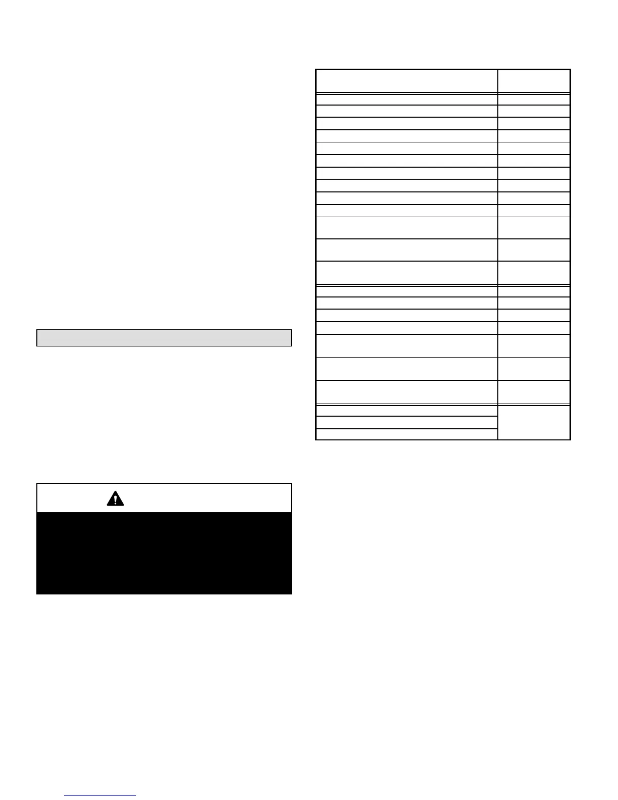
Pipe & Fittings Specifications
All pipe, fittings, primer and solvent cement must conform
with American National Standard Institute and the Ameri-
can Society for Testing and Materials (ANSI/ASTM) stan-
dards. The solvent shall be free flowing and contain no
lumps, undissolved particles or any foreign matter that ad-
versely affects the joint strength or chemical resistance of
the cement. The cement shall show no gelation, stratifica-
tion, or separation that cannot be removed by stirring. Re-
fer to the table 2 below for approved piping and fitting ma-
terials.
CAUTION
Solvent cements for plastic pipe are flammable liq-
uids and should be kept away from all sources of
ignition. Do not use excessive amounts of solvent
cement when making joints. Good ventilation should
be maintained to reduce fire hazard and to minimize
breathing of solvent vapors. Avoid contact of cement
with skin and eyes.
TABLE 2
PIPING AND FITTINGS SPECIFICATIONS
PIPE & FITTING MATERIAL
ASTM
SPECIFICATION
Schedule 40 PVC (Pipe) D1785
Schedule 40 PVC (Cellular Core Pipe) F891
Schedule 40 PVC (Fittings) D2466
Schedule 40 CPVC (Pipe) F441
Schedule 40 CPVC (Fittings) F438
SDR−21 PVC or SDR−26 PVC (Pipe) D2241
SDR−21 CPVC or SDR−26 CPVC (Pipe) F442
Schedule 40 ABS Cellular Core DWV (Pipe) F628
Schedule 40 ABS (Pipe) D1527
Schedule 40 ABS (Fittings) D2468
ABS−DWV (Drain Waste & Vent)
(Pipe & Fittings)
D2661
PVC−DWV (Drain Waste & Vent)
Pipe & Fittings)
D2665
PRIMER & SOLVENT CEMENT
ASTM
SPECIFICATION
PVC & CPVC Primer F656
PVC Solvent Cement D2564
CPVC Solvent Cement F493
ABS Solvent Cement D2235
PVC/CPVC/ABS All Purpose Cement For Fit-
tings & Pipe of the same material
D2564, D2235,
F493
ABS to PVC or CPVC Transition Solvent
Cement
D3138
CANADA PIPE & FITTING & SOLVENT
CEMENT
MARKING
PVC & CPVC Pipe and Fittings
ULCS636
PVC & CPVC Solvent Cement
ABS to PVC or CPVC Transition Cement
Use PVC primer and solvent cement or ABS solvent cement
meeting ASTM specifications, refer to Table 2. As an alter-
nate, use all purpose cement, to bond ABS, PVC, or CPVC
pipe when using fittings and pipe made of the same materi-
als. Use transition solvent cement when bonding ABS to ei-
ther PVC or CPVC.
Low temperature solvent cement is recommended. Metal or
plastic strapping may be used for vent pipe hangers. Uni-
formly apply a liberal coat of PVC primer for PVC or use a
clean dry cloth for ABS to clean inside socket surface of fit-
ting and male end of pipe to depth of fitting socket.
Canadian Applications Only − Pipe, fittings, primer
and solvent cement used to vent (exhaust) this ap-
pliance must be certified to ULC S636 and supplied by a
single manufacturer as part of an approved vent (ex-
haust) system. When bonding the vent system to the fur-
nace, use ULC S636 approved One−Step Transition Ce-
ment to bond the pipe to the flue collar, or to bond the 90°
elbow or reducing 90° elbow to the flue collar. In addi-
tion, the first three feet of vent pipe from the furnace flue
collar must be accessible for inspection.
Table 3 lists the available exhaust termination kits, as well
as vent pipe equivalencies which must be used when siz-
ing vent pipe. All Lennox vent terminations are PVC.
 Loading...


