Page 14
Vent Piping Guidelines
The G43UF can be installed as either a Non−Direct Vent
or a Direct Vent gas central furnace.
NOTE − In Non-Direct Vent installations, combustion air is
taken from indoors and flue gases are discharged outdoors.
In Direct Vent installations, combustion air is taken from out-
doors and flue gases are discharged outdoors.
Intake and exhaust pipe sizing in Direct Vent applications
and exhaust pipe sizing in Non-Direct Vent applications −−
Size pipe according to tables 4 and 5. Table 4 lists the mini-
mum equivalent vent pipe lengths permitted. Table 5 lists
the maximum equivalent pipe lengths permitted.
Maximum vent length is defined as:
Total length (linear feet) of pipe,
Plus Equivalent length (feet) of fittings,
Plus Equivalent length (feet) of termination.
NOTE − Include ALL pipe and ALL fittings, both
indoors and outdoors.
Regardless of the diameter of pipe used, the standard roof
and wall terminations described in section Exhaust Piping
Terminations should be used. Exhaust vent termination
pipe is sized to optimize the velocity of the exhaust gas as
it exits the termination. Refer to table 6.
NOTE − The exhaust pipe should be offset a minimum of 12
inches to avoid the possibility of water droplets being re-
leased from the exhaust termination. The minimum ex-
haust vent length is 15 ft. Shorter exhaust vent lengths may
result in the discharge of water droplets from the exhaust
termination, in spite of the 12−inch vertical offset.
Each 90° elbow (including those provided with the furnace)
of any diameter is equivalent to 5 feet (1.52m) of vent pipe
of the same diameter. Two 45° elbows are equivalent to
one 90° elbow of the same diameter. One 45° elbow is
equal to 2.5 feet (.76m) of vent pipe of the same diameter.
In some applications which permit the use of several differ-
ent sizes of vent pipe, a combination vent pipe may be
used. Contact the Application Department for assistance in
sizing vent pipe in these applications.
NOTE − The flue collar on all models is sized to accommo-
date 2" Schedule 40 flue pipe. When vent pipe which is
larger than 2" must be used in an upflow application, a 2"
elbow must be applied at the flue collar in order to proper-
ly transition to the larger diameter flue pipe. This elbow
must be added to the elbow count used to determine ac-
ceptable vent lengths. Assign an equivalent feet value to
this elbow according to the larger size pipe being used.
Contact the Application Department for more information
concerning sizing of vent systems which include multiple
pipe sizes.
Use the following steps to correctly size vent pipe diameter.
Refer to Vent Pipe Size Determination Worksheet on
Page 48.
1 − Determine the vent termination and its corresponding
equivalent feet value according to table 3.
2 − Determine the number of 90° elbows required for both
indoor and outdoor (e.g. snow riser) use. Calculate the
corresponding equivalent feet of vent pipe.
3 − Determine the number of 45° elbows required for both
indoor and outdoor use. Calculate the corresponding
equivalent feet of vent pipe.
4 − Determine the length of straight pipe required.
5 − Add the total equivalent feet calculated in steps 1
through 4 and compare that length to the maximum
values given in table 5 for the proposed vent pipe di-
ameter. If the total equivalent length required exceeds
the maximum equivalent length listed in the appropri-
ate table, evaluate the next larger size pipe.
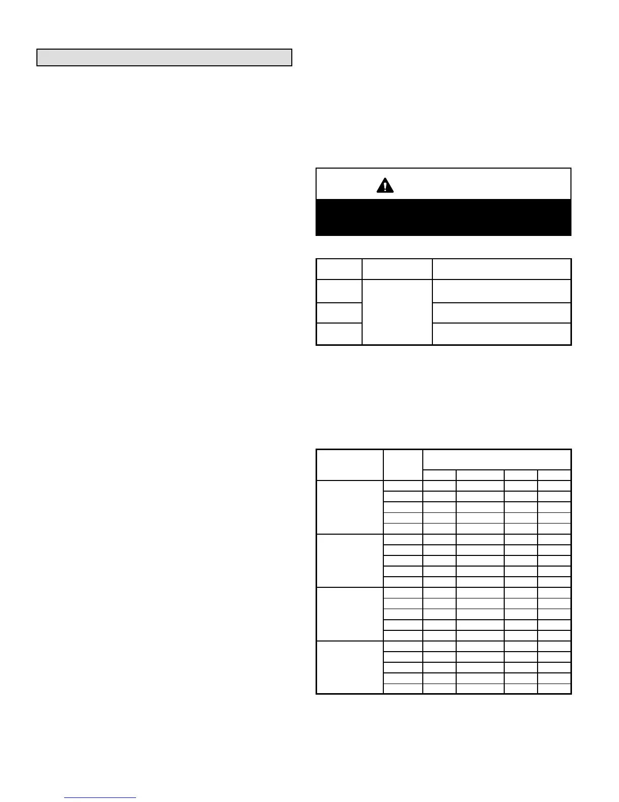
IMPORTANT
Do not use screens or perforated metal in exhaust
terminations. Doing so will cause freeze−ups and
may block the terminations.
TABLE 4
MINIMUM VENT PIPE LENGTHS
G43UF
MODEL
MIN. EQUIV.
VENT LENGTH
EXAMPLE
045, 070,
090
15 ft.*
5 ft. plus 2 elbows of 2", 2−1/2", 3"
or 4" diameter pipe
110**
5 ft. plus 2 elbows of 2", 2−1/2", 3" or
4" diameter pipe
135***
5 ft. plus 2 elbows of 3" or 4"
diameter pipe
*Any approved termination may be added to the minimum equivalent length
listed.
**G43UF−48C−110, G43UF−110H and G43UF−60C−110 must have 90° street
ell (supplied or field replacement Canadian kit) installed directly into unit flue
collar.
***G43UF−60D−135 must have 3" to 2" reducing ell (supplied or field replace-
ment Canadian kit) installed directly into unit flue collar.
TABLE 5
MAXIMUM VENT PIPE LENGTHS
DIRECT (2 PIPE) AND NON−DIRECT (1 PIPE) APPLICATIONS
ALTITUDE
G43UF
MODEL
MAXIMUM EQUIVALENT VENT
LENGTH FEET
2" dia. 2−1/2" dia. 3" dia. 4" dia.
0 − 2000
(0 − 609 m)
045 110 135 160 250
070 70 135 160 250
090 50 100 125 225
110* 30 70 125 200
135** n/a n/a ***125 180
2001 − 4500
(610 − 1371 m)
045 110 135 160 250
070 70 135 160 250
090 50 100 125 225
110* 20 70 125 200
135** n/a n/a ***90 180
4501−7500
(1372−2286 m)
045 110 135 160 250
070 70 135 160 250
090 30 100 125 225
110* n/a 70 125 200
135** n/a n/a ***90 180
7501 − 10000
(2287 − 3048 m)
045 110 135 160 250
070 70 135 160 250
090 n/a 100 125 225
110* n/a 70 125 200
135** n/a n/a ***90 180
n/a −− Not allowed.
*G43UF−48C−110 and G43UF−60C−110 must have 90° street ell (supplied)
installed directly into unit flue collar.
**G43UF−60D−135 must have 3" to 2" reducing ell (supplied) installed directly
into unit flue collar.
***90° elbows used in configuration of G43UF−60D−135 vent, must be lim-
ited to 3" sweep elbows.
 Loading...


