Page 38
Other Unit Adjustments
Primary Limit
The primary limit is located on the heating compartment
vestibule panel. This limit is factory set and requires no ad-
justment.
Flame Rollout Switches (Two)
These manually reset switches are located on the burner
box. If tripped, check for adequate combustion air before
resetting.
Pressure Switch
The pressure switch is located in the heating compartment
on the combustion air inducer. This switch checks for prop-
er combustion air inducer operation before allowing igni-
tion trial. The switch is factory−set and requires no adjust-
ment.
Temperature Rise
After the furnace has been started and supply and return air
temperatures have been allowed to stabilize, check the
temperature rise. If necessary, adjust the blower speed to
maintain the temperature rise within the range shown on
the unit nameplate. Increase the blower speed to decrease
the temperature. Decrease the blower speed to increase
the temperature rise. Failure to adjust the temperature rise
may cause erratic limit operation.
Fan Control
The fan on time of 45 seconds is not adjustable. The fan off
delay(amount of time that the blower operates after the
heat demand has been satisfied) may be adjusted by
changing the jumper position across the five pins on the
integrated control. The unit is shipped with a factory fan off
setting of 90 seconds. The fan off delay affects comfort and
is adjustable to satisfy individual applications. Adjust the
fan off delay to achieve a supply air temperature between
90° and 110°F at the exact moment that the blower is de−
energized. Longer off delay settings provide lower return
air temperatures; shorter settings provide higher return air
temperatures. See figure 47.
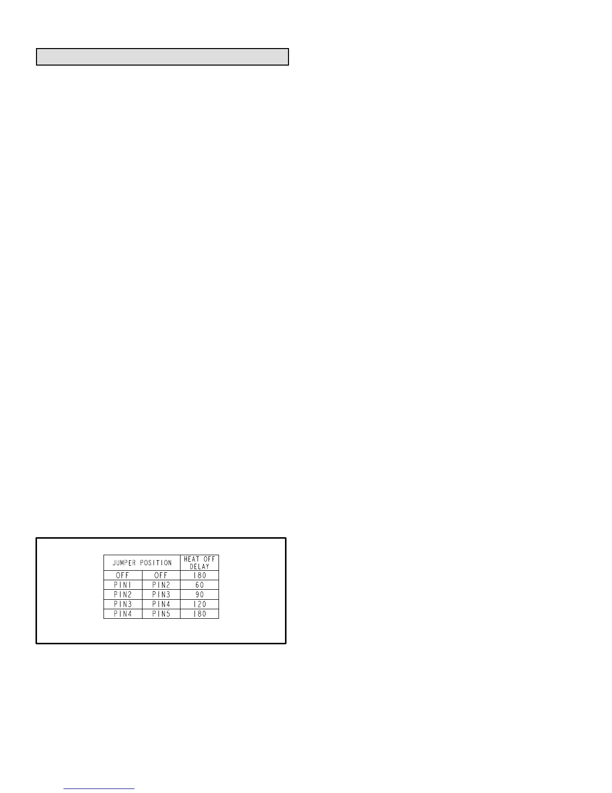
FAN-OFF TIME ADJUSTMENT
To adjust fan−off timing, reposition jumper across pins to
achieve desired setting.
FIGURE 47
Thermostat Heat Anticipation
Set the heat anticipator setting (if adjustable) according to
the amp draw listed on the wiring diagram that is attached
to the unit.
Electrical
1 − Check all wiring for loose connections.
2 − Check for the correct voltage at the furnace (furnace
operating).
3 − Check amp-draw on the blower motor.
Motor Nameplate__________Actual__________
NOTE − Do not secure the electrical conduit directly to the
air ducts or structure.
Blower Speeds
NOTE − CFM readings are taken external to unit with a dry
evaporator coil and without accessories.
Turn off electrical power to furnace.
Remove blower access panel.
Disconnect existing speed tap at control board speed
terminal.
NOTE − Termination of any unused motor leads must be
insulated.
Refer to blower speed selection chart on unit wiring dia-
gram for desired heating or cooling speed. See Blower
performance data beginning on Page 39.
Connect selected speed tap at control board speed
terminal.
Resecure blower access panel.
Turn on electrical power to furnace.
Electronic Ignition
The integrated control has an added feature of an internal
Watchguard control. The feature serves as an automatic re-
set device for ignition control lockout caused by ignition fail-
ure. This type of lockout is usually due to low gas line pres-
sure. After one hour of continuous thermostat demand for
heat, the Watchguard will break and remake thermostat de-
mand to the furnace and automatically reset the control to
begin the ignition sequence.
Exhaust and Air Intake Pipe
1 − Check exhaust and air intake connections for tightness
and to make sure there is no blockage.
2 − Is pressure switch closed? Obstructed exhaust pipe
will cause unit to shut off at pressure switch. Check ter-
mination for blockages.
3 − Reset manual flame rollout switches on burner box
cover.
Failure To Operate
If the unit fails to operate, check the following:
1 − Is the thermostat calling for heat?
2 − Are access panels securely in place?
3 − Is the main disconnect switch closed?
4 − Is there a blown fuse?
5 − Is the filter dirty or plugged? Dirty or plugged filters will
cause the limit control to shut the unit off.
6 − Is gas turned on at the meter?
7 − Is the manual main shut-off valve open?
8 − Is the internal manual shut-off valve open?
9 − Is the unit ignition system in lock out? If the unit locks out
again, inspect the unit for blockages.
 Loading...


