Page 11
TABLE 6
DIAGNOSTIC CODES
Diagnostic LEDs are labeled DS1 and DS2. See figure 4 for location of diagnostic LEDs.
DS1 DS2 DESCRIPTION
SIMULTANEOUS
SLOW FLASH
SIMULTANEOUS
SLOW FLASH
Power on − Normal operation.
Also signaled during cooling and continuous fan.
SIMULTANEOUS
FAST FLASH
SIMULTANEOUS
FAST FLASH
Normal operation − signaled when heating demand initiated at thermostat.
SLOW FLASH ON
Primary, secondary, backup secondary or rollout limit switch open. Limits must
close within 3 minutes or unit goes into 1 hour Watchguard.
OFF SLOW FLASH
Low prove switch open;
OR: Blocked inlet/exhaust vent;
OR: Low prove switch closed prior to activation of combustion air inducer.
OFF FAST FLASH
High prove switch open;
OR: Blocked inlet/exhaust vent;
OR: High prove switch closed prior to activation of combustion air inducer.
ALTERNATING
SLOW FLASH
ALTERNATING
SLOW FLASH
Watchguard −− burners failed to ignite; OR limit open more than 3 minutes;
OR lost flame sense 5 times in one heating cycle;
OR pressure switch opened 5 times in one heating cycle.
SLOW FLASH OFF Flame sensed without gas valve energized.
ON ON
ON
OFF
Circuit board failure or control wired incorrectly. Check 24 and 115 volts to board.
OFF ON
FAST FLASH SLOW FLASH Main power polarity reversed. Switch line and neutral.
SLOW FLASH FAST FLASH Low flame signal. Measures below 0.23 microAmps. Replace flame sense rod.
ALTERNATING
FAST FLASH
ALTERNATING
FAST FLASH
The following conditions are sensed during the ignitor warm−up period only:
1) Improper main ground;
2) Broken ignitor; OR: Open ignitor circuit;
3) Line voltage below 75 volts.
(If voltage lower than 75 volts prior to ignitor warm-up, control will signal waiting on
call from thermostat, and will not respond.
NOTE − Slow flash rate equals 1 Hz (one flash per second). Fast flash rate equals 3 Hz (three flashes per second).
Low flame sense current = 0.17−0.22 microAmps.
B−Blower Compartment
1. Blower Motor (B3) and Capacitor (C4)
All G61MP units use direct drive blower motors. All motors
are 120V permanent split capacitor motors to ensure maxi-
mum efficiency. Ratings for capacitors will be on motor
nameplate. See SPECIFICATIONS section for motor speci-
fications.
NOTE − Shafts on 1 HP motors have 2 flat sides and are
matched with blower wheels with 2 set screws.
2. Secondary Limit Controls (S21)
The secondary limits (S21) on G61MP units are located in the
blower compartment on the back side of the blower housing.
See figure 5. All G61MP units are equipped with two secon-
dary limts. When excess heat is sensed in the blower compart-
ment, the limit will open. If the limit is open, the furnace control
energizes the supply air blower and closes the gas valve. The
limit automatically resets when unit temperature returns to nor-
mal. The switch is factory set to open at 125°F and cannot be
adjusted.
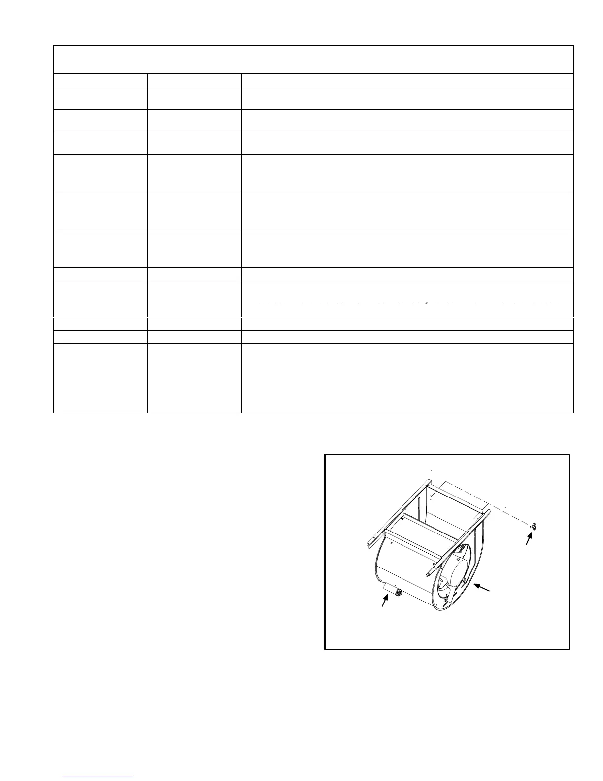
FIGURE 5
SUPPLY AIR BLOWER
AND SECONDARY LIMITS
SECONDARY
LIMIT (S)
CAPACITOR
MOTOR/BLOWER
ASSEMBLY
To Remove Blower From Unit: Disconnect Power, Remove Control
Box, Remove Bolts and Unplug Motor Wires From Control Board.
Then Slide Out Front of Unit.
 Loading...