Page 25
Details of Intake and Exhaust Piping Terminations for
Direct Vent Installations
NOTE − In Direct Vent installations, combustion air is taken
from outdoors and flue gases are discharged to outdoors.
Intake and exhaust pipes may be routed either horizontally
through an outside wall or vertically through the roof. In at-
tic or closet installations, vertical termination through the
roof is preferred. Figures 20 through 28 show typical ter-
minations.
1. Exhaust and intake exits must be in same pressure
zone. Do not exit one through the roof and one on the
side. Also, do not exit the intake on one side and the
exhaust on another side of the house or structure.
2. Intake and exhaust pipes should be placed as close
together as possible at termination end (refer to il-
lustrations). Maximum separation is 3" (76mm) on roof
terminations and 6" (152mm) on side wall termina-
tions.
3. If necessary, install a field−provided reducer to adapt
larger vent pipe size to termination pipe size.
4. On roof terminations, the intake piping should termi-
nate straight down using two 90° elbows (See figure
20).
5. Exhaust piping must terminate straight out or up as
shown. In rooftop applications, a reducer may be re-
quired on the exhaust piping at the point where it exits
the structure to improve the velocity of exhaust away
from the intake piping. See table 14.
NOTE − Care must be taken to avoid recirculation of
exhaust back into intake pipe.
6. On field supplied terminations for side wall exits, ex-
haust piping should extend a minimum of 12 inches
(305mm) beyond the outside wall. Intake piping
should be as short as possible. See figure 21.
7. On field supplied terminations, a minimum separation
distance between the end of the exhaust pipe and the
end of the intake pipe is 8 inches (203mm).
8. If intake and exhaust piping must be run up a side wall
to position above snow accumulation or other obstruc-
tions, piping must be supported every 3 ft. (.9m) as
shown in figure 12. Refer to figure 24 for proper piping
method. In addition, WTK wall termination kit must be
extended for use in this application. See figure 27.
When exhaust and intake piping must be run up an
outside wall, the exhaust piping is reduced to 1−1/2"
(38mm) after the final elbow. The intake piping may be
equipped with a 90° elbow turndown. Using turndown
will add 5 feet (1.5m) to the equivalent length of the
pipe.
9. Based on the recommendation of the manufacturer, a
multiple furnace installation may use a group of up to
four termination kits WTK assembled together hori-
zontally, as shown in figure 26.
TABLE 14
EXHAUST PIPE TERMINATION SIZE REDUCTION
G61MP
MODEL
Exhaust Pipe Size Termination Pipe Size
045 and 070 2", 2−1/2", 3" or 4" 1−1/2"
090 2", 2−1/2", 3" or 4" 2"
110 2−1/2", 3" or 4" 2"*
135 3" or 4" 2"*
*Approved 3" concentric termination kit terminates with 2−5/8" ID pipe.
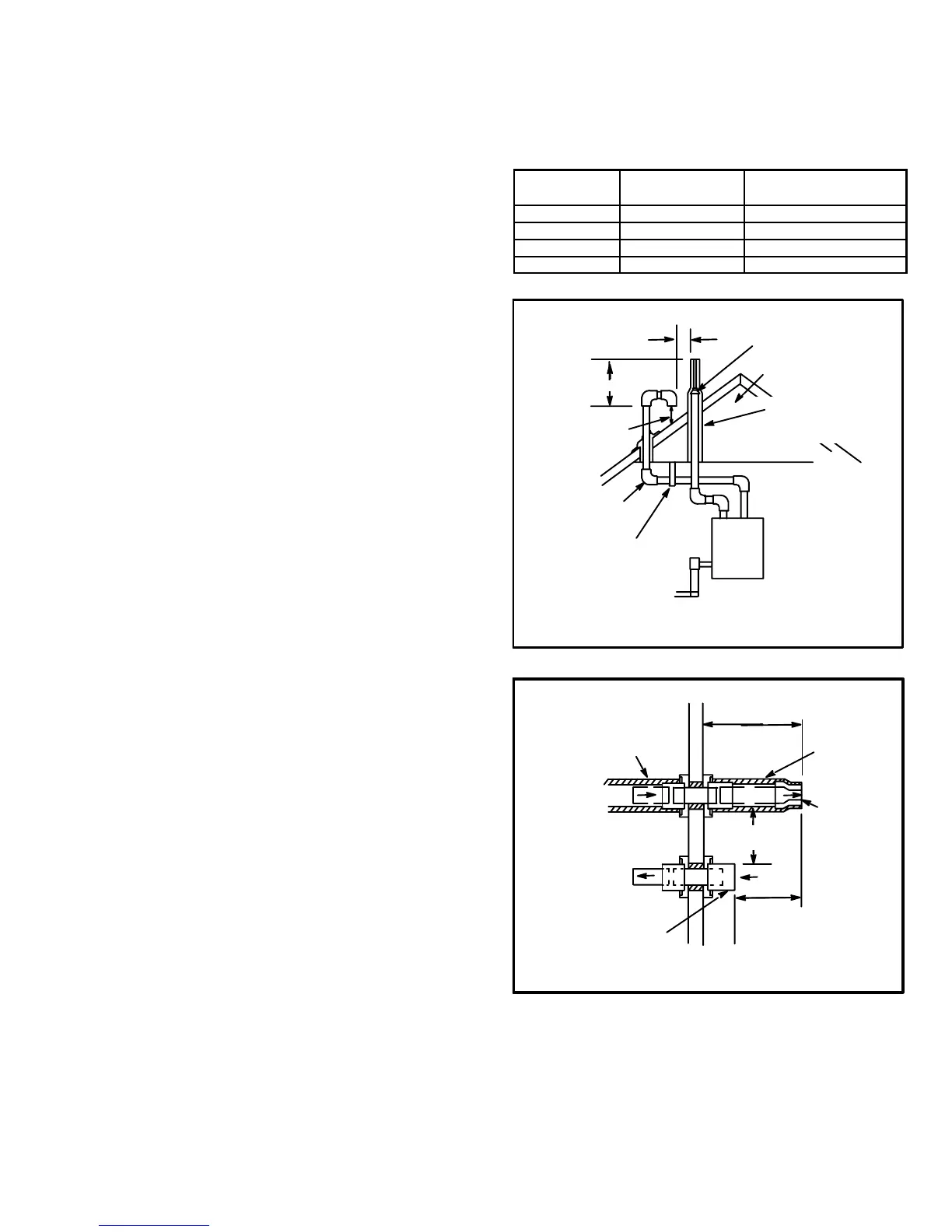
FIGURE 20
DIRECT VENT ROOF TERMINATION KIT
(15F75 or 44J41)
UNCONDITIONED
ATTIC SPACE
1/2" (13) FOAM
INSULATION IN
UNCONDITIONED
SPACE
SIZE TERMINATION
PIPE PER TABLE 14.
3(76) MAX.
12" (305) ABOVE
AVERAGE SNOW
ACCUMULATION
3" (76) OR
2" (51) PVC
PROVIDE SUPPORT
FOR INTAKE AND
EXHAUST LINES
8" (203) MIN
Inches(mm)
FIGURE 21
8" (203)
MINIMUM
1/2" (13) ARMAFLEX
INSULATION IN
UNCONDITIONED SPACE
12" (305) MAX.
(unless supported)
1/2" (13)
ARMAFLEX
INSULATION
6" (152)
MAXIMUM
2" (51) PVC
COUPLING
OUTSIDE
WALL
Inches (mm)
TOP VIEW WALL RING KIT
(15F74)
SIZE
TERMINATION
PIPE PER
TABLE 14.
FIELD−
PROVIDED
REDUCER MAY
BE REQUIRED
TO ADAPT
LARGER VENT
PIPE SIZE TO
TERMINATION
 Loading...