Page 20
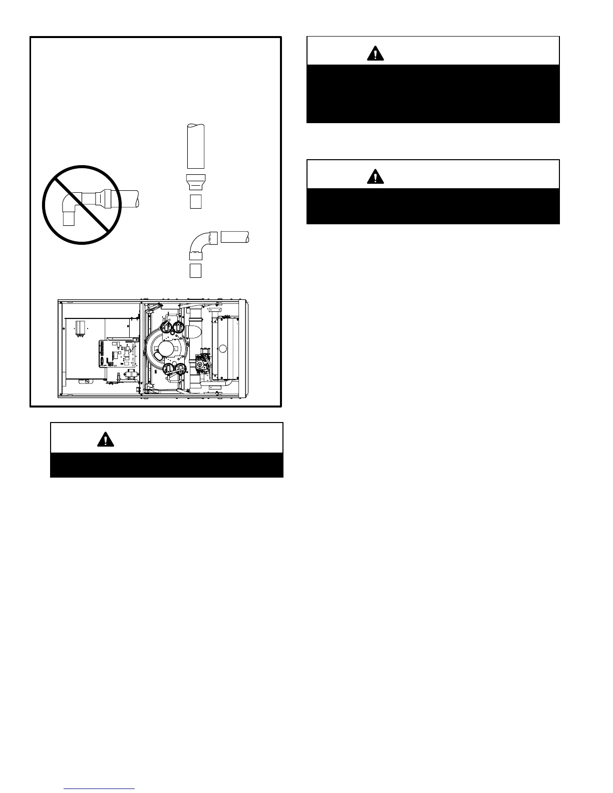
FIGURE 14
TYPICAL EXHAUST PIPE CONNECTIONS
HORIZONTAL DIRECT OR NON-DIRECT VENT
APPLICATIONS
(Horizontal Right-Hand Air
Discharge Application Shown)
G61MP−36B−045
G61MP−36B−070
G61MP−48C−090
G61MP−60C−090
G61MP−48C−110*
G61MP−60C−110*
G61MP−60C−135*
G61MP−36B−045
G61MP−36B−070
G61MP−48C−090
G61MP−60C−090
*Limit pipe length to 2"
in G61MPV−110 and
−135 applications.
DO NOT transition from
smaller to larger pipe
size in horizontal runs.
2"
2"
2"
2"*
2−1/2",
3", OR
4"
REDUCER
IMPORTANT
Exhaust piping and condensate trap must be
installed on the same side of the unit.
2. All horizontal runs of exhaust pipe must slope back to-
ward unit. A minimum of 1/4" (6mm) drop for each 12"
(305mm) of horizontal run is mandatory for drainage.
Horizontal runs of exhaust piping must be supported ev-
ery 5 feet (1.52m) using hangers.
NOTE − Exhaust piping should be checked carefully to
make sure there are no sags or low spots.
3. On the opposite side of the cabinet, glue the provided
2" vent plug into the unused flue collar.
4. Route piping to outside of structure. Continue with
installation following instructions given in piping ter-
mination section.
CAUTION
Do not discharge exhaust into an existing stack or
stack that also serves another gas appliance. If verti-
cal discharge through an existing unused stack is re-
quired, insert PVC pipe inside the stack until the end
is even with the top or outlet end of the metal stack.
CAUTION
The exhaust vent pipe operates under positive pres-
sure and must be completely sealed to prevent leak-
age of combustion products into the living space.
Intake Piping
The G61MP furnace may be installed in either direct vent
or non−direct vent applications. In non−direct vent applica-
tions, when intake air will be drawn into the furnace from the
surrounding space, the indoor air quality must be consid-
ered and guidelines listed in Combustion, Dilution and Ven-
tilation Air section must be followed.
The G61MP unit is designed for either left−side or right−side
air intake connections in either upflow or downflow applica-
tions. In horizontal applications, air intake must be brought
in through the top. Intake air piping is independent of ex-
haust piping.
Follow the next four steps when installing the unit in direct
vent applications, where combustion air is taken from out-
doors and flue gases are discharged outdoors. The pro-
vided air intake screen must not be used in direct vent ap-
plications.
1 − Cement intake piping in slip connector located on the
side of the burner box.
2 − Use a #7 sheet metal screw to secure the intake pipe to
the connector, if desired. A pilot indentation is provided in
the slip connector to assist in locating and starting the fas-
tener.
3 − Glue the provided 2" plug into the unused air intake con-
nector on the opposite side of the cabinet.
4 − Route piping to outside of structure. Continue with instal-
lation following instructions given in general guide lines for
piping terminations and in intake and exhaust piping ter-
minations for direct vent sections. Refer to figure 15 for
pipe sizes.
 Loading...