Page 48
IX−SURELIGHT
®
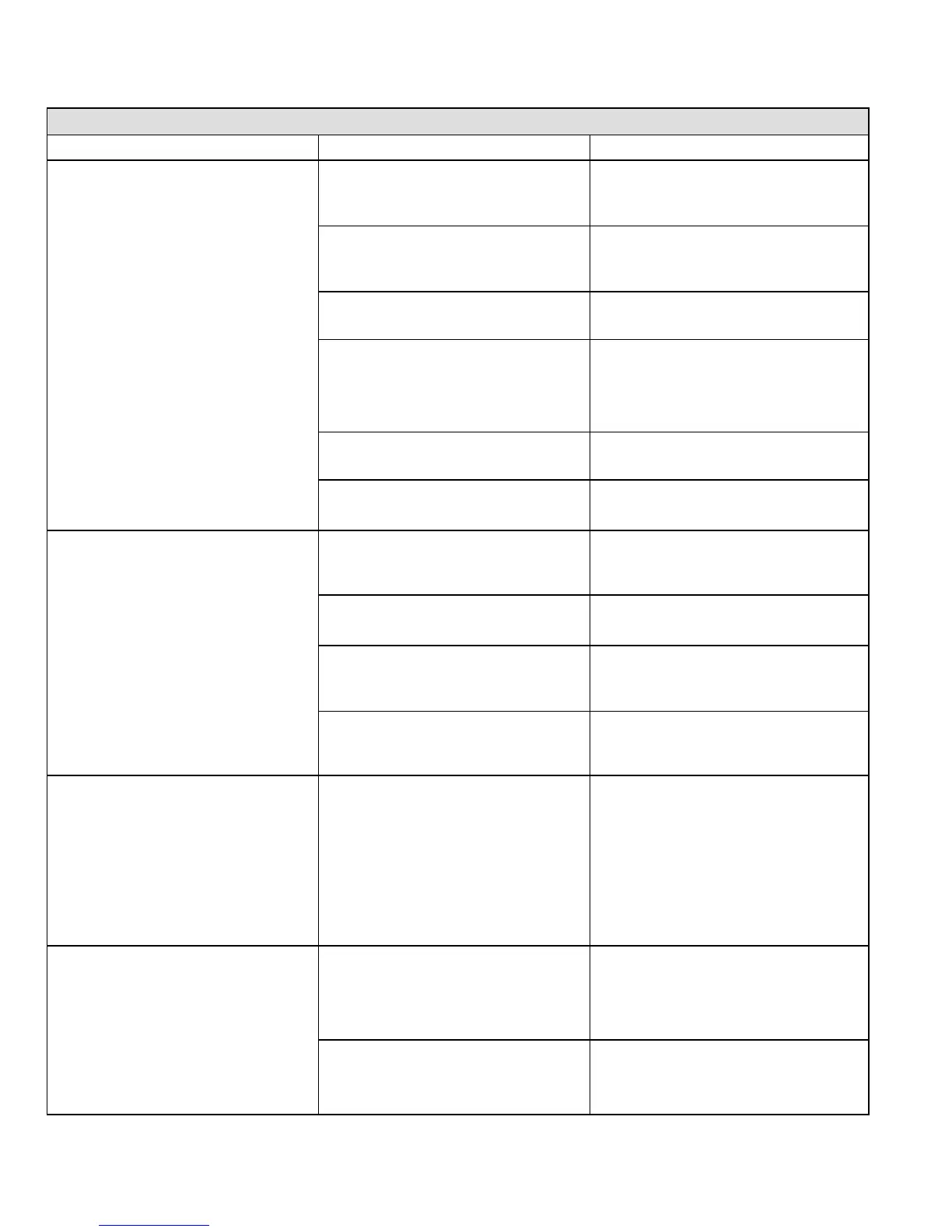
CONTROL TROUBLESHOOTING CHART
UPON INITIAL POWER UP, REMOVE ALL THERMOSTAT DEMANDS TO THE UNIT
PROBLEM: 1 UNIT FAILS TO OPERATE IN THE COOLING, HEATING, OR CONTINUOUS FAN MODE
Condition Possible Cause Corrective Action / Comments
1.1
− Both diagnostic lights fail to light up.
1.1.1
Main voltage 120V not supplied to unit.
ACTION 1 − Check 120V main voltage.
Determine cause of main power failure.
LED#1−Off
LED#2−Off
1.1.2
Miswiring of furnace or improper con-
nections.
ACTION 1 − Check for correct wiring of 120V to
power make up box and transformer.
ACTION 2 − Check 24V wiring to control board.
1.1.3
Blown fuse
ACTION 1 − Replace fuse.
ACTION 2 − If fuse still blows, check for short.
1.1.4
Door interlock switch failure.
ACTION 1 − Check that door switch is activated
when door is closed.
ACTION 2 − Check wire connections to switch, re-
place loose connectors.
ACTION 3 − Check continuity of switch in closed
position. Replace if defective.
1.1.5
Transformer Failure.
ACTION 1 − Check that transformer output is
24V. Replace if defective.
1.1.6
Failed control board.
ACTION 1 − If all the above items have been
checked, replace board.
1.2
− Diagnostic lights flash the roll−out
code.
1.2.1
Roll−out switch open.
ACTION 1 − Manually reset the roll−out switch
by pushing the top button.
ACTION 2 − Determine the cause of the roll−out
switch activation before leaving furnace.
.
1.2.2
Roll−out switch failure.
ACTION 1 − Check continuity across roll−out
switch. Replace roll−out switch if switch is reset
but does not have continuity.
LED#1−On,
LED#2−Slow Flash
1.2.3
Mis iring or improper connections at
ACTION 1 − Check wiring connections to switch
Miswiring or improper connections at
roll−out switch.
−
ec
w
r
ng connect
ons to sw
tc
.
1.2.4
9 pin connector failure
ACTION 1 − Check 9−pin connector for proper
connection to control board.
ACTION 2 − Check continuity of the multi plug
pin.
1.3
− On initial power−up the comb. air in-
r
n
n
r
iz
.
.
− Diagnostic lights flash the reverse
polarity code.
1.3.1
120V main power polarity reversed.
ACTION 1 − Check the 120V has line and neutral
correctly input into control.
ACTION 2 − Reverse the line and neutral at the
120V field connection.
LED#1−Fast Flash,
LED#2−Slow Flash.
1.4
− On initial power up the combustion
air inducer does not energize.
− Diagnostic lights flash normal power
on o
eration.
1.4.1
Open combustion air inducer motor
circuit.
ACTION 1 − Check for 120V to combustion air
inducer. If no power, check wire and connec-
tions.
.
LED#1−Slow Flash
LED#2−Slow Flash
1.4.2
Failed combustion air inducer motor.
ACTION 1 − If power is present at blower, replace
blower.
 Loading...