Page 22
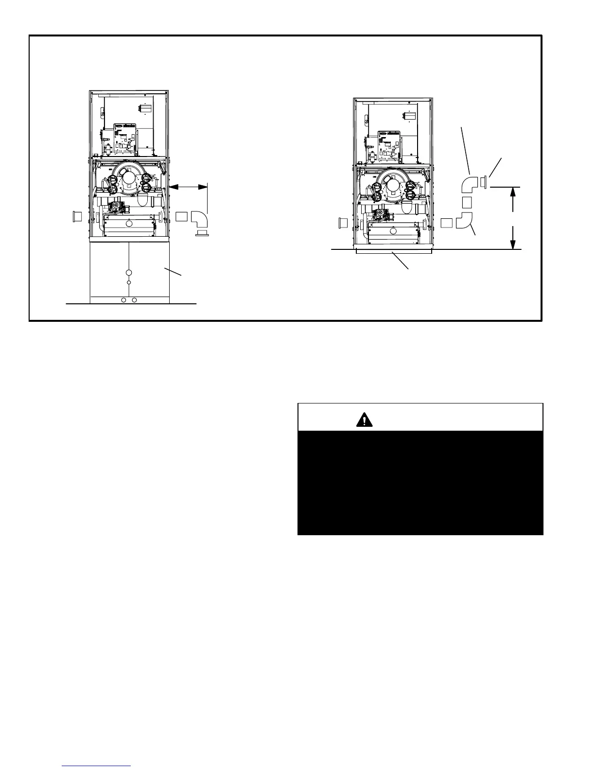
TYPICAL AIR INTAKE PIPE CONNECTIONS
DOWNFLOW NON-DIRECT VENT APPLICATIONS
(Right-Hand Exit in Downflow Applications Shown)
FIGURE 18
PLUG
(Must be
glued in
place)
6 in. Max.
PLUG
(Must be
glued in
place)
Downflow Additive Flloor Base
18 in.
Downflow
Evaporator
Coil
2"
2" SWEEP
ELL
2" SWEEP ELL
INTAKE DEBRIS
SCREEN
(Provided)
INTAKE
DEBRIS
SCREEN
(Provided)
NOTE − Debris screen and sweep ell may be rotated, so that
screen may be positioned to face forward, backward or to the side.
1 − Use field−provided materials and the factory−provided
air intake screen to route the intake piping as shown in
figures 17 and 18. Maintain a minimum clearance of 3"
(76mm) around the air intake opening. The air intake
opening (with the protective screen) should always be
directed either downward or straight out. Use 2" pipe
and fittings only and make sure that the air intake does
not extend more than 6" beyond the G61MP cabinet.
The air intake connector must not be located near
the floor. To avoid this complication in downflow
applications which do not include a downflow
evaporator coil, the intake air routing should be modi-
fied as shown in figure 18.
2 − Use a #7 sheet metal screw to secure the intake pipe to
the connector, if desired. A pilot indentation is provided in
the slip connector to assist in locating and starting the fas-
tener.
3 − Glue the provided 2" plug into the unused air intake con-
nector on the opposite side of the cabinet.
Testing for Proper Venting and Sufficient Combustion Air
(Non−Direct Vent Applications Only)
WARNING
CARBON MONOXIDE POISONING HAZARD!
Failure to follow the steps outlined below for each
appliance connected to the venting system being
placed into operation could result in carbon monox-
ide poisoning or death.
The following steps shall be followed for each ap-
pliance connected to the venting system being
placed into operation, while all other appliances con-
nected to the venting system are not in operation.
After the G61MP gas furnace has been started, the follow-
ing test should be conducted to ensure proper venting and
sufficient combustion air has been provided to the G61MP,
as well as to other gas-fired appliances which are separate-
ly vented. The test should be conducted while all ap-
pliances (both in operation and those not in operation) are
connected to the venting system being tested. If the vent-
ing system has been installed improperly, or if provisions
have not been made for sufficient amounts of combustion
air, corrections must be made as outlined in the previous
section.
1 − Seal any unused openings in the venting system.
2 − Visually inspect the venting system for proper size and
horizontal pitch. Determine there is no blockage or re-
striction, leakage, corrosion, or other deficiencies
which could cause an unsafe condition.
 Loading...