Page 19
C− Venting Practices
The thickness of construction through which vent pipes
may be installed is 24" (610mm) maximum and 3" (76mm)
minimum. If a G61MP furnace replaces a furnace which
was commonly vented with another gas appliance, the size
of the existing vent pipe for that gas appliance must be
checked. Without the heat of the original furnace flue prod-
ucts, the existing vent pipe is probably oversized for the
single water heater or other appliance. The vent should be
checked for proper draw with the remaining appliance.
1. Use recommended piping materials for exhaust pip-
ing.
2. Secure all joints so that they are gas-tight using ap-
proved cement.
Suspend piping using hangers at a minimum of every 5
feet (1.52m) for schedule
40 PVC and every 3 feet
(.91m) for ABS−DWV, PVC−
DWV, SPR−21 PVC, and
SDR−26 PVC piping. A suit-
able hanger can be fabri-
cated by using metal or
plastic strapping or a large
wire tie.
3. In areas where piping penetrates joists or interior
walls, hole must be large enough to allow clearance on
all sides of pipe through center of hole using a hanger.
4. Isolate piping at the point where it exits the outside wall
or roof in order to prevent transmission of vibration to
the structure.
5. When furnace is installed in a residence where unit is
shut down for an extended period of time, such as a
vacation home, make provisions for draining conden-
sate collection trap and lines.
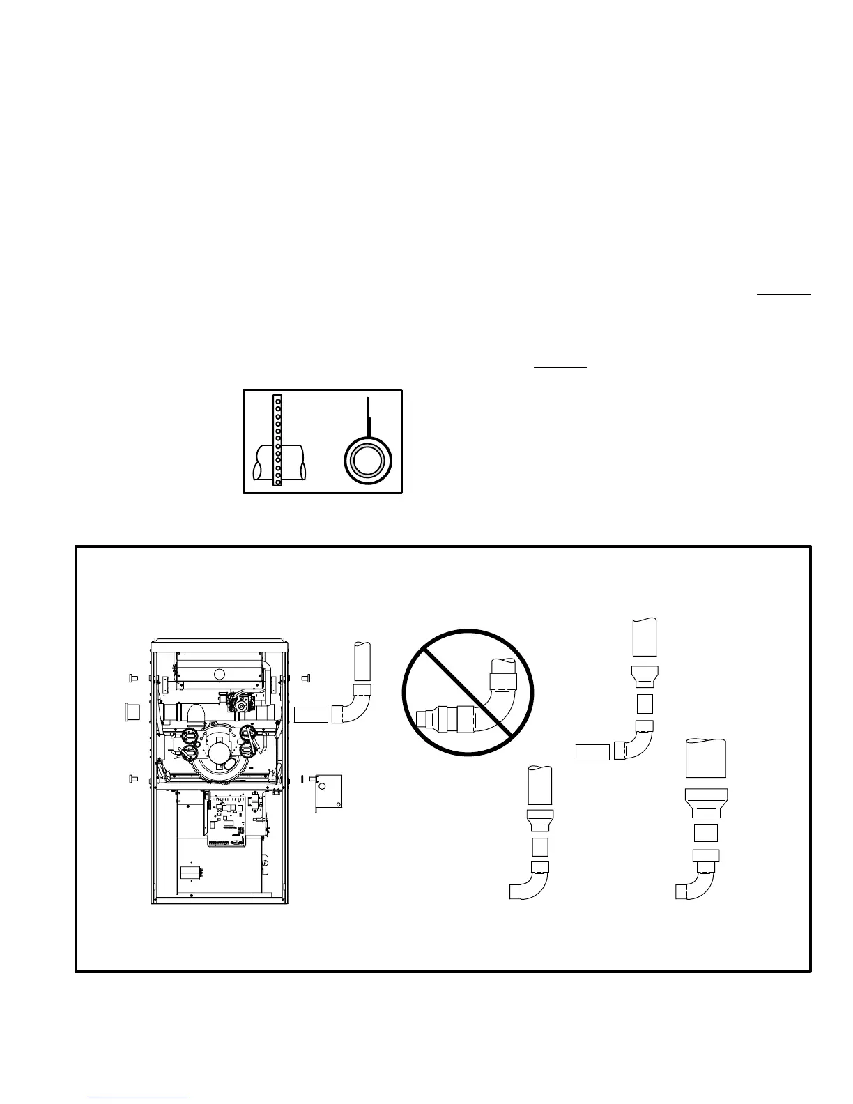
Exhaust Piping
NOTE − A 2" diameter street ell is strapped to the blower
deck of 48C−110 and 60C−110 units. Street ell must be
glued directly into the unit flue collar. See figure 13. A 3" to
2" reducing ell is strapped to the blower deck of the
60D−135 units. In upflow or downflow applications, the
reducing ell must be glued directly into the unit flue collar.
1. Choose the appropriate side for venting in upflow or
downflow positions. Exhaust piping exits from the top
of the unit in horizontal air discharge applications.
Glue the field−provided exhaust vent pipe (or provided
street ell or reducing ell in upflow or downflow applica-
tions) to the flue collar. All cement joints should be
made according to the specifications outlined in ASTM
D 2855. Refer to pipe and fittings specifications and
gluing procedures.
CONDENSATE
TRAP
(Must be installed
on same side as
exhaust piping)
VENT PLUG
(Must be
glued in
place)
PLUG
PLUG PLUG
TYPICAL EXHAUST PIPE CONNECTIONS AND CONDENSATE TRAP INSTALLATION
IN UPFLOW OR DOWNFLOW DIRECT OR NON-DIRECT VENT APPLICATIONS
(Right-Hand Exit in Upflow Application Shown)
FIGURE 13
*2" diameter street elbow provided.
**3" diameter reducing elbow provided.
G61MP−110 with
2−1/2", 3", OR 4"
vent pipe
G61MP−135 with
3" OR 4" vent pipe
2"*
3"**
2"***
2"
REDUCER
G61MP−045, 070
or 090 with 2−1/2",
3", or 4" vent pipe
2−1/2",
3", OR
4"
3"
REDUCER
(use only if
4" pipe is
required)
4"
***Limit pipe length to 2".
2”
2”
2−1/2",
3", OR
4"
REDUCER
2”
2”
2”
FIGURE 12
STRAPPING
(metal, plastic
or large wire
ties)
 Loading...