11
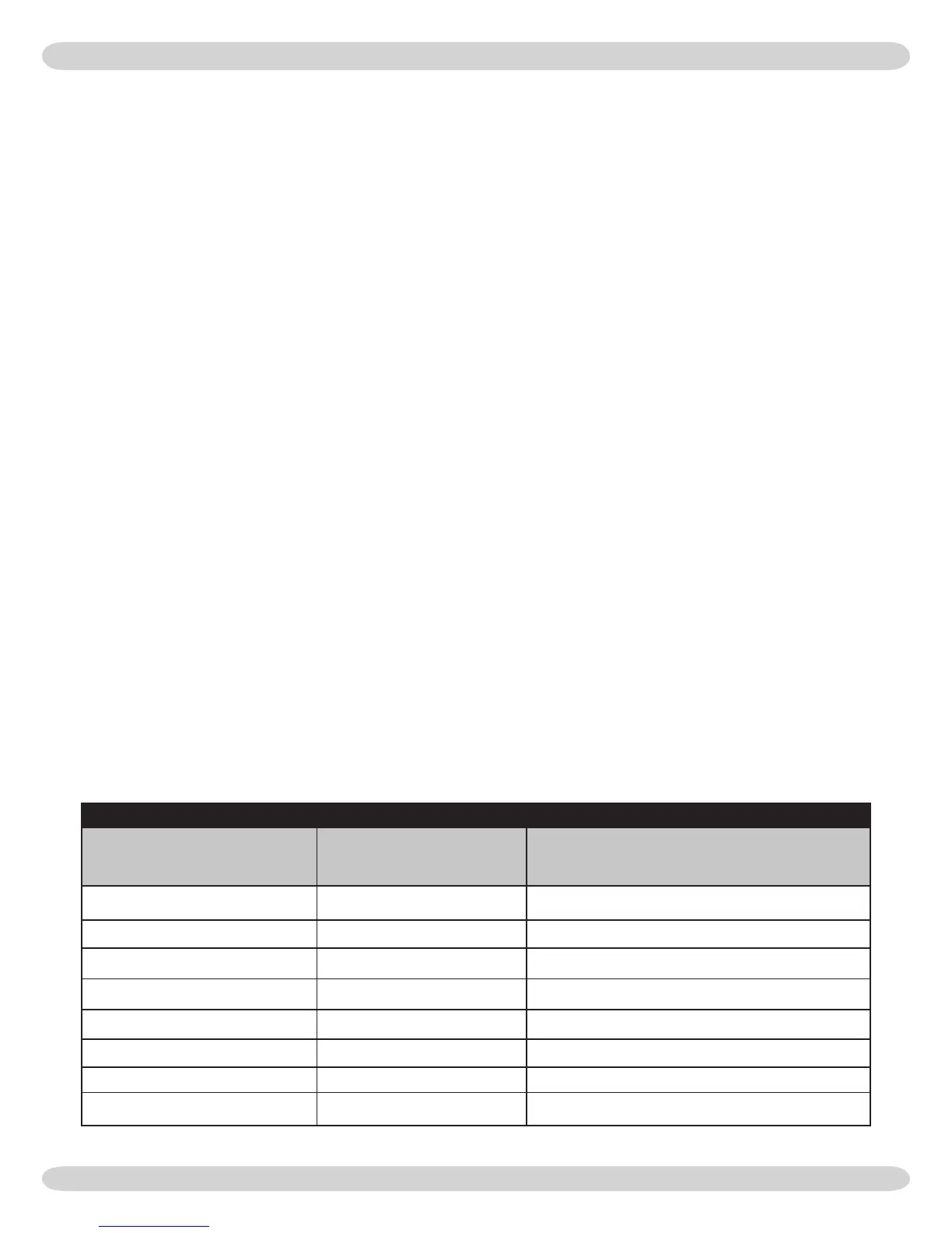
TABLE #2 -
BOILER CLEARANCES
Unit
Combustible Clearance
Inch (mm)
Accessibility, Cleaning, and Servicing
Inch (mm)
Top 1 (25.4) 8 (203.2)
Left Side 1 (25.4) 24 (609.6)
Right Side 8 (203.2) -
Base 1 (25.4) -
Front 0 (0) 24 (609.6)
Back 1 (25.4) -
Intake/Vent Piping 0 (0) -
Near Boiler Hot Water Piping 1 (25.4) -
All distances measured from the cabinet of the boiler.
Select a location which is level, central to the piping sys-
7.
tems served and as close to the vent and air intake termi-
nals as possible.
Accessibility clearances, if more stringent (i.e. larger clear-
8.
ances) than required re protection clearances, must be
used for the boiler installation. Accessibility clearances
may be achieved with the use of removable walls or parti-
tions.
e boiler is approved for installation in closets and on
9.
combustible oors. is boiler shall NOT be installed on
carpeting.
e clearances shown in Table #2 indicate required clear-
10.
ances per IAS listing. A minimum 1” clearance must be
maintained between combustible construction and each
of the le, top and back surfaces of the boiler. A minimum
8” clearance is required on the right side, to allow room
for the inlet air pipe. An 18” clearance must be maintained
at a side where passage is required to access another side
for cleaning or servicing, inspection or replacement of
any parts that normally may require such attention. Allow
at least 24” at the front and le side and 8” at the top for
servicing. No clearances are required to venting or com-
bustion air intake piping.
Equipment shall be installed in a location which facilitates
11.
the operation of venting and combustion air intake piping
systems as described in this manual.
Advise owner of boiler to keep venting and combustion
12.
air intake passages free of obstructions. both the venting
and combustion air intake piping systems connected to
the outdoors must permit ow through the piping systems
without restrictions for the boiler to operate.
e boiler shall be installed such that the automatic gas ig-
13.
nition system components are protected from water (drip-
ping, spraying, rain, etc.) during operation and service
(circulator replacement, control replacement, etc.).
is boiler requires a dedicated direct vent system. In a direct
vent system, all air for combustion is taken directly from
outside atmosphere, and all ue products are discharged to
outside atmosphere.
Combustion air and vent pipe connections must terminate to-
gether in the same atmospheric pressure zone, either through
the roof or sidewall (roof termination preferred). See
Figures
#9 & #10
(in Combustion Air And Vent Pipe section near
center of this manual) for required clearances.
 Loading...