42
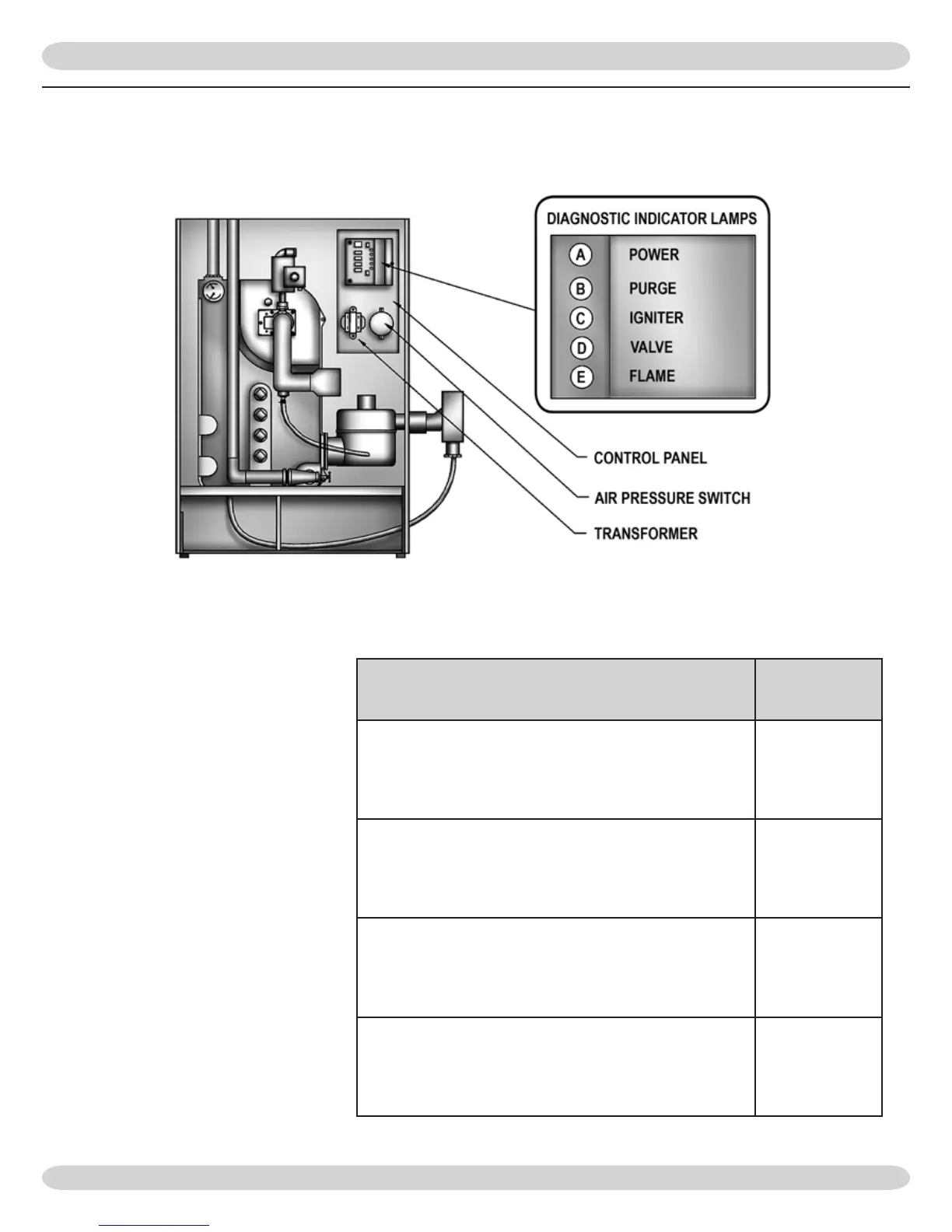
e sequence can be followed via the
diagnostic indicator lamps on the Hon-
eywell S9301A integrated boiler control
in
Figure #16.
is is the normal
sequence of operation. A more detailed
sequence of operation containing po-
tential faults can be found in the service
hints section.
SEQUENCE OF OPERATION
“DIAGNOSTIC
INDICATOR
LAMPS”
“Power ON, boiler standing by. Lamp A is illuminated
indicating 2 Volt power is being supplied to the inte-
grated control.”
A.
B.
C.
D.
E.
Thermostat calls for heat, energizing system circulator
A.
B.
C.
D.
E.
“Integrated boiler control goes through self check of
internal circuitry (1-2 seconds) and energizes draft
inducer”
A.
B.
C.
D.
E.
“Draft inducer comes up to speed and establishes com-
bustion airow, causing the normally open differential
pressure air proving switch contacts to close. Lamp B is
illuminated indicating that combustion airow is proved
and the 15 second pre purge cycle”
A.
B.
C.
D.
E.
 Loading...