4
Terminals, Wiring Recommendations and Electrical Characteristics
IMPORTANT
Use 18AWG unshielded thermostat cable (eld-provided) for power terminals (R and C). Highly recommend using 18 - 22AWG shielded thermostat cable for
communications terminals (I+ and I-) which will help eliminate any noise interference.
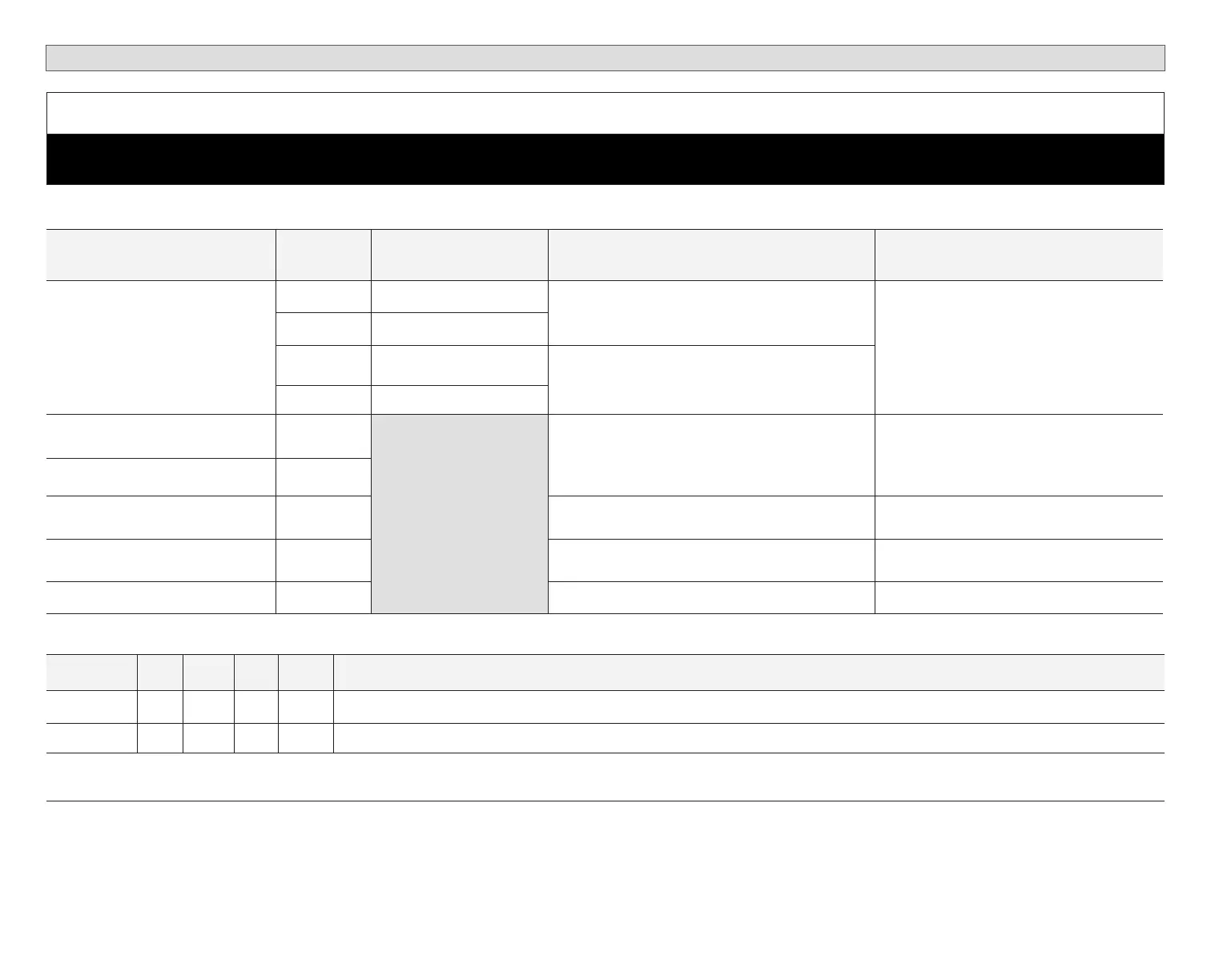
Table 4. Terminals and Wiring Recommendations
Component to Component Terminal Purpose Recommended Wiring Specications
Maximum Distance between
Components
Damper Control Module to Indoor Unit
or 17A20 Zone Sensor
R 24VAC input
18AWG, (unshielded thermostat cable (eld-provided)
197 feet (50 meters)
C 24VAC return
I+ RS-BUS I+
18 - 22AWG shielded (recommended) (eld-
provided)
I- RS-BUS I-
Damper Control Module to 50A93
Freezestat
Freezestat
18AWG, unshielded thermostat cable (eld-provided) 197 feet (50 meters)
Damper Control Module to 93G35
Freezestat
Freezestat
Damper Control Module to 27W13
High Pressure Switch
Pressure
Switch
18AWG, unshielded thermostat cable (eld-provided) 197 feet (50 meters)
Damper Control Module to Discharge
Air Temperature Sensor
DATS 18AWG, unshielded thermostat cable (eld-provided). 30 feet (9 meters)
Damper Control Module to Dampers Dampers 18AWG, unshielded thermostat cable (eld-provided) Check with damper manufacturer
Table 5. Damper Control Module Electrical Characteristics
Min Nom Max Units Comments
Input Voltage 18 24 30 VAC System and Damper Power
Input Current 2 Amp @ 24VAC and all four dampers closed
(All values are @ 25VAC, 60Hz. 25 Degrees Celsius [77°F] unless noted)
 Loading...


