6
Table 6. DATS Temperature / Resistance Chart
Sensor
°C °F (ohm)
VDC (Volts) Sensor
°C °F (ohm)
VDC (Volts)
37.8 100 5,819 0.405 90.8 195 895 0.072
40.6 105 5,193 0.368 93.4 200 829 0.067
43.4 110 4,654 0.335
Outdoor Air Temperature Sensor (OATS)
The optional outdoor air (temperature) sensor (OATS) (X2658) wiring dis-
tance to the iComfort S30 should not exceed 150 feet (45 meters) when
wired as specied in “Table 4. Terminals and Wiring Recommendations” on
page 4.
Installation of OATS must comply with the following requirements:
• Sensor wiring must be run to avoid touching or being close to high voltage
wiring and light ballast.
• Choose a protected outdoor location away from direct sunlight or other heat
sources (usually on the north side of the building).
• Ensure that water will neither collect on, nor wash over the sensor.
• Do not locate the sensor near driveways or similar heat-absorbing masses
which may reect stored heat energy onto the sensor and send inaccurate
information to the thermostat.
• Locate the sensor away from attic and soft vents, or furnace venting pipes.
• Do not locate the sensor directly above an air conditioner or heat pump.
Transformer Phasing
‘The indoor unit and zone damper transformers must be in -phase since both
are connected to the damper control module. Follow the instructions below for
phasing both transformers.
1. Connect the damper control module indoor R and C to the indoor unit R
and C.
2. Connect the external 24VAC transformer to the damper control module
DMPR XFMR C terminal only. Check voltage from indoor R to External
XFMR wire R. If voltage is not phased then switch before connecting wires.
This will keep damaging voltage off of the control module.
» In -phase voltage will be the difference of both XFMR voltages approxi-
mately less than 5VAC.
» Out-of-phase voltage will be the sum of both XFMR voltages approxi-
mately greater than 50VAC.
3. Verify voltage between the damper control module indoor R and DPMR
XFMR R terminals after wires are connected.
Ci−i+R
INDOOR
DMPR
XFMR
SYS
XFMR
Lennox Communicating
Furnace or Air
Handler
Ci−i+R
External 24VAC
Transformer
R
Damper Control
Module
Volt Meter
C
R
C
DMPRXFMR
Remove R to R wire when
testing. Replace wire when
testing is completed.
Factory Default
Figure 3. Conrming Correct Transformer Phasing
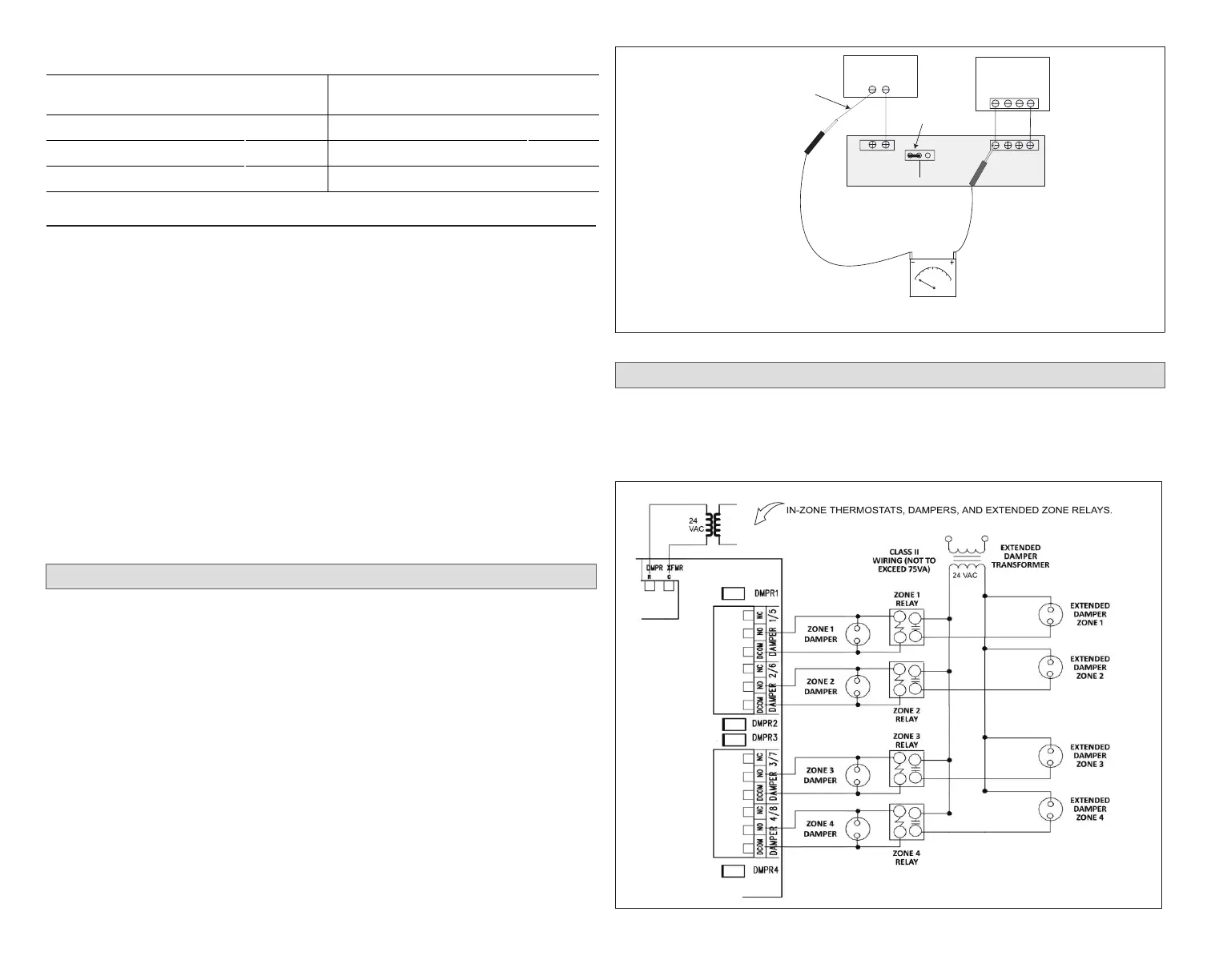
Damper Wiring
See table 1 to determine the minimum damper transformer VA requirements
based on the number of zones being installed. If extended zone dampers
are used then see gure 2 for damper, transformer and zone relay wiring
requirements.
MAIN
POWER
MAIN
POWER
DAMPER TRANSFORMER
– POWERS DAMPER CONTROL MODULE,
Figure 4. Damper and Extended Damper Wiring Diagram
 Loading...


