5
Sensors
Discharge Air Temperature Sensor (DATS)
Installation of discharge air temperature sensor (DATS) must comply with the
following requirements:
• Installed downstream of the heat exchanger or electric heat elements.
• It must be placed in free airow, where other accessories (such as humidiers,
UV lights, etc.) will not interfere with its accuracy.
• Wiring distance between the integrated furnace and air handler controls
or damper control module and the discharge air sensor must not exceed
maximum distance as referenced in “Table 4. Terminals and Wiring
Recommendations” on page 4.
• DATS is highly recommended for all systems that include a variable capacity
outdoor unit in order to provided more precise dehumidication operation.
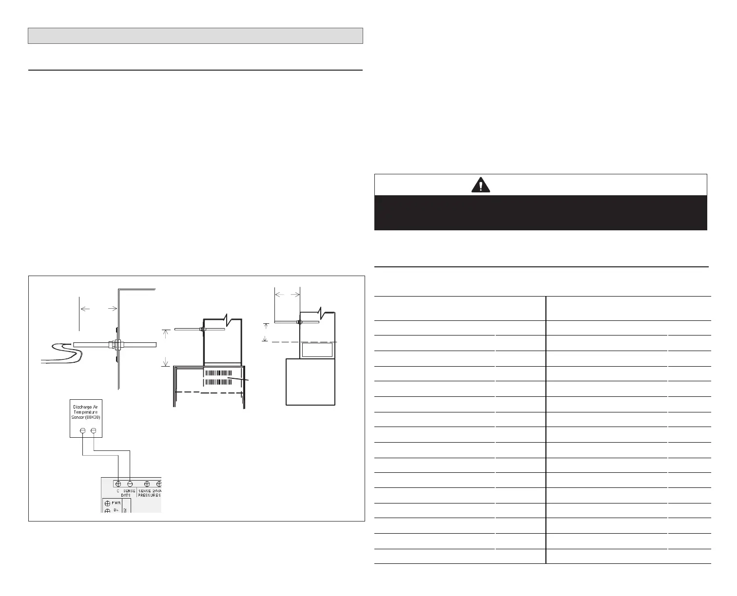
The included discharge air temperature sensor (88K38) monitors the supply
air. “Figure 2. Discharge Air Temperature Sensor Installation (Typical Up-Flow
Furnace)” shows the discharge air temperature sensor. This electronic sensor’s
probe is inserted into the discharge air plenum to gather air temperature data
for the zone control module.
Do not use backside
coil
FURNACE
SIDE
VIEW
10 (254)
AIR HANDLER
SIDE VIEW
ECB
Electric
Heat
Strips
PLENUM
SENSOR
MOUNTING
DETAIL
19
(486)
Damper Control Module
11”
Front location preferred /
sides are optional
11”
DAS Starting
Point
Figure 2. Discharge Air Temperature Sensor Installation (Typical Up-
Flow Furnace)
• When possible, position the sensor some distance away from the coil rather
than in the immediate coil area.
• The DATS should be located at least 19 inches above the air handler unit
and 10 inches above cooling coil with a furnace.
• Locate the tip of the sensor 1/2 the depth of the plenum, and centered over
the discharge airow, side- to -side in the discharge plenum
• Fasten the sensor bracket to the plenum with two self-tapping sheet metal
screws.
• Connect wires to DATS on damper control module, NOT on the Lennox
communicating indoor unit control.
NOTE: FOR UNITS WITH HUMIDITROL—Discharge air sensor temperature
(DATS) MUST be located on the output side of the EDA (if used; see
Humiditrol Zoning Accessory Installation 507944-xx).
IMPORTANT
If the DAT sensor has failed, shorted or not installed, iHarmony will only
operate in central mode. This mode is also indicated by the DCM central
mode LED being on. There is no notication by the thermostat for this issue.
Discharge Air Temperature Sensor (88K38) Temperature, Resistance
and Voltage Chart
Table 6. DATS Temperature / Resistance Chart
Sensor
°C °F (ohm)
VDC (Volts) Sensor
°C °F (ohm)
VDC (Volts)
-6.6 20 46,134 1.513 46.2 115 4,169 0.304
-3.9 25 39,869 1.425 49.0 120 3,749 0.277
-1.1 30 34,520 1.335 51.8 125 3,368 0.252
1.7 35 29,936 1.247 54.5 130 3,037 0.229
4.4 40 26,104 1.161 57.3 135 2,750 0.209
7.2 45 22,764 1.077 60.0 140 2,489 0.191
10.1 50 19,842 0.993 62.8 145 2,250 0.174
12.8 55 17,406 0.916 65.7 150 2,033 0.158
15.6 60 15,294 0.842 68.5 155 1,847 0.145
18.4 65 13,442 0.772 71.3 160 1,678 0.132
21.2 70 11,849 0.706 73.9 165 1,536 0.121
23.9 75 10,501 0.647 76.8 170 1,397 0.111
26.7 80 9,282 0.589 79.7 175 1,272 0.101
29.5 85 8,233 0.537 82.2 180 1,170 0.094
32.3 90 7,322 0.489 85.1 185 1,070 0.086
35.0 95 6,523 0.445 87.8 190 982 0.079
 Loading...


