8
Staged Heat Pump Units
Should the pressure switch open during heat pump heating second stage
operation:
• Lennox communicating thermostat will downstage the heat pump from
second-stage to rst-stage heating operation in order to bring the system
pressure down to a point where the switch closes again.
• If the unit is already running in rst-stage when the pressure switch opens,
the unit will shut off.
• If the switch closes within 60 seconds, then the Lennox communicating series
thermostat may send a demand for second-stage heat pump if needed.
• If the switch does not close within 60 seconds, the Lennox communicating
thermostat stops heat pump heating and satises the heating demand with
backup heat (backup heat is either electric or gas) regardless of the ambient
temperature being above the high balance point.
The heat pump is used again on the next call provided the pressure switch has
closed; otherwise backup heat is used on subsequent heating calls until the
pressure switch closes.
Variable Capacity Heat Pump Units (XP20 and XP25)
If the pressure switch opens during heat pump heating operation:
• Lennox communicating series thermostat will respond by sending a HP heat
demand with the demanded rate equal to the current rate 25%. (i.e. the
switch opens during a 90% heating demand,
• Lennox communicating thermostat then sends a demand for 90 25 = 65%)
If new calculated rate is below the minimum for the unit, minimum demand
is sent.
• If the switch closes within 60 seconds, then the Lennox communicating
series thermostat may change the demand for the heat pump as determined
by the DATS.
• If the switch does not close within 60 seconds, the Lennox communicating
series thermostat stops heat pump heating and satises the heating demand
with backup heat (backup heat is either electric or gas) regardless of the
ambient temperature being above the hi balance point.
The heat pump is used again on the next call provided the pressure switch has
closed; otherwise backup heat is used on subsequent heating calls until the
pressure switch closes.
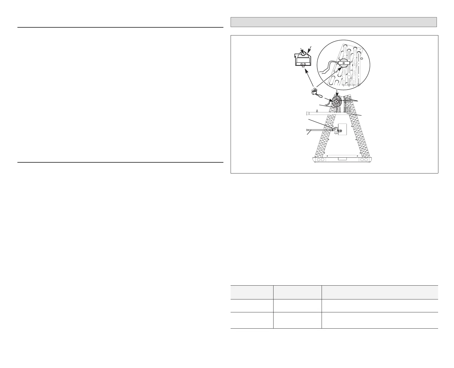
Freezestat (Optional)
CLIP
COPPER
LINE
EXPANSION
VALVE
FREEZESTAT
SUCTION
MANIFOLD
LIQUID LINE
LAST HAIRPINS
COPPER LINES
Figure 6. Typical Freezestat Installation - Indoor Coil
This optional component is only required if there is a small zone with little
airow which is causing the indoor coil to freeze up. However, normal return air
temperature should prevent this from occurring. The addition of the freezestat
will provide for added protection.
NOTE: The damper control module comes from the factory with a insertion
bridge installed on the freezestat terminals (see “Figure 7. Damper
Control Jumpers LEDs and Connections” on page 14). Do not
remove unless a freezestat is connected. Outdoor unit will not operate
if insertion bridge is removed (missing) and no freezestat is installed.
The table following lists available freezestats for use with the damper control
module.
Table 7. Available Freezestats
Catalog Number Piping Size Description
93G35 ⅜” Opens at 29°F, and closes at 58°F
50A93 ⅝” Opens at 36°F, and closes at 58°F
Suggested Freezestat Installation Method
The following is the recommended method for installation of the freezestat for
 Loading...


