10
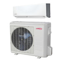
Four Field-provided Anchor Bolts
Figure 20. Securing Outdoor Unit to Slab
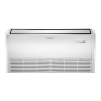
Four Field-Provided
Anchor Bolts
Figure 21. Securing Outdoor Unit to Rails
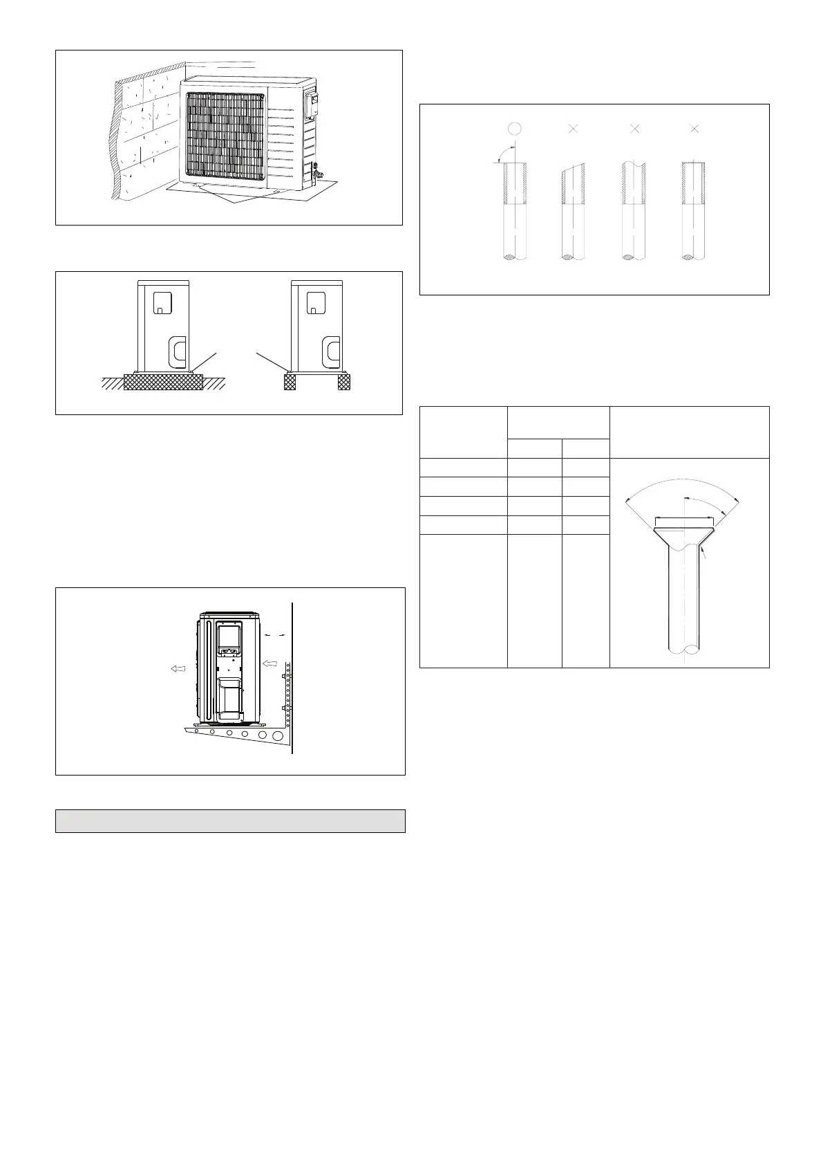
Securing Outdoor Unit to Hanging Brackets
If the outdoor unit is installed on eld-provided wall
mounting brackets, use lag bolts or equivalent to secure
the outdoor unit to the bracket. Minimum rear clearance
can be reduced to 6 inches (152 mm) when mounted
on brackets and with no obstructions on the other three
sides. Allow for moisture disposal when placing units
above one another.
Air Outlet
Air Inlet
6 in
152 mm
Figure 22. Securing Outdoor Unit to Brackets
Refrigerant Piping Connections
Field piping consists of two copper lines connecting the
outdoor unit to the indoor unit. “Table 3. Refrigerant Piping
and Indoor Unit Connection Sizes” on page 11 lists
the connection sizes. The connections are made using
the provided brass are nuts at the end of the refrigerant
piping connections.
1. Choose the correct pipe sizes for your application
using “Table 3. Refrigerant Piping and Indoor Unit
Connection Sizes” on page 11.
2. Conrm that you are using the correct diameter piping.
3. Determine the necessary piping length required for
the application.
4. Cut the selected pipes with a pipe cutter. Make the
cuts at and smooth as illustrated in “Figure 23.
Cutting Piping”.
Figure 23. Cutting Piping
5. Insulate the copper piping.
6. Insert a are nut onto each pipe before aring.
7. Use “Table 2. Flaring Pipe” to properly are the pipe.
Table 2. Flaring Pipe
Pipe Diameter
Flare Dimension
A (mm)
Flare Shape
Min Max
1/4” 8.3 8.7
R0.4~0.8
A
45
°
90°
4
-
+
3/8” 12.0 12.4
1/2” 15.4 15.8
5/8” 18.6 19.1
3/4” (22.9) 22.9 23.3
8. After aring the pipe, temporarily sealed pipe ends
with adhesive tape to avoid contaminants from
entering the pipes.
9. The seal on the unit refrigerant piping connections
should remain in place until the last possible moment.
This will prevent dust or water from getting into the
refrigerant piping before it is connected.
10. CAREFULLY adjust refrigerant piping connections to
suit the application.
11. Slowly loosen one of the are nuts to release the
factory nitrogen charge from the indoor units only.
12. Remove the are nuts from the connections on the
unit and discard the seal from each of the piping
connections.
13. Slide the are nuts onto the ends of the eld-provided
refrigerant piping before using a suitable aring tool to
are the end of the copper pipe.
14. Apply recommended HFC-410A refrigerant lubricant
to the outside of the ared refrigerant lines.

 Loading...