8
Installation of Indoor Unit on Wall Mounting Plate
1. A length of eld-provided exible condensate piping
should be connected to the drain prior to securing the
unit to the wall mounting plate.
2. If the factory-provided refrigerant piping connections
and eld-provided exible condensate piping are long
enough to enable nal eld connections after unit is
installed on wall mounting plate, use eld-provided
tape to bundle them together.
3. The utility bundle may be routed out of the back of
the unit or out either side. If the bundle is to be routed
out the back through an external wall, feed the utility
bundle through the wall sleeve. If the utility bundle is
to be routed out of the side of the indoor unit and up
an inside wall, carefully form the utility bundle so that
it makes a gentle 90° turn.
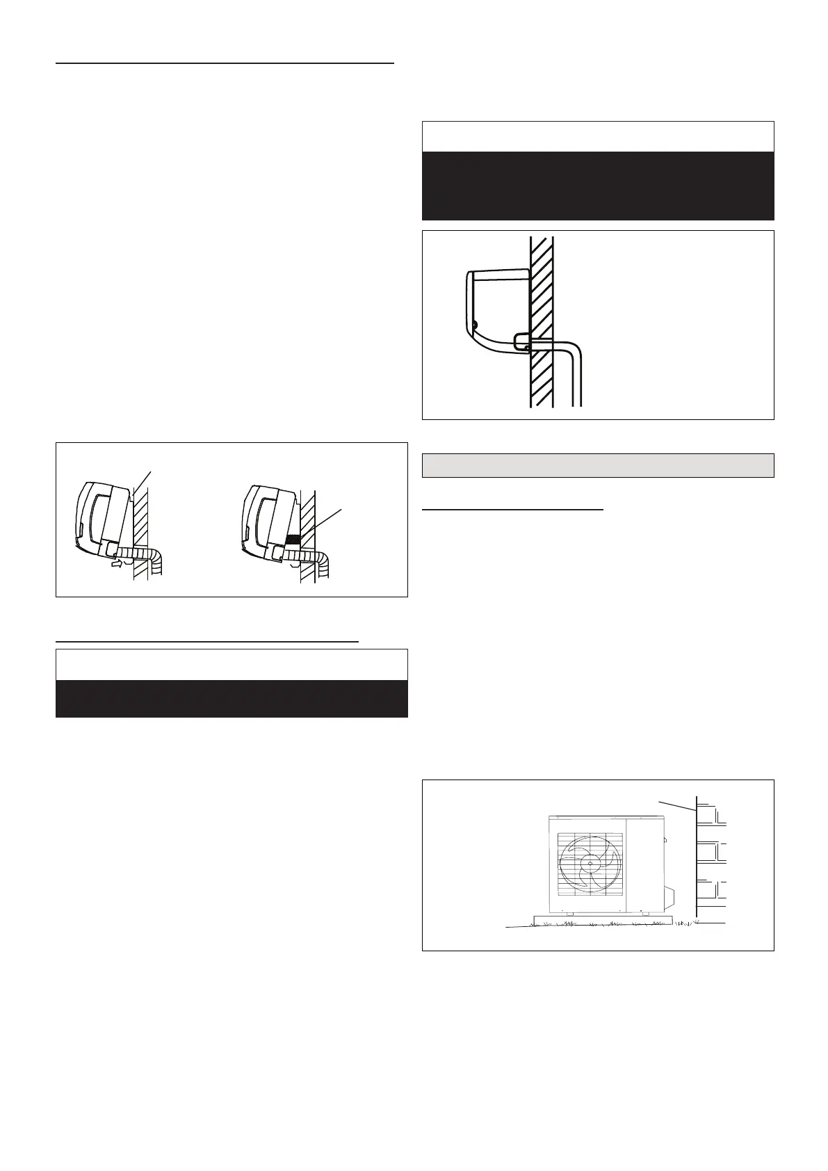
4. Align the back of the indoor unit with the hooks at the
top of the wall mounting plate. Move the unit from side
to side to make sure that it settles securely.
5. The bottom of the unit can be lifted to facilitate
refrigerant piping and condensate drain connections,
if necessary.
TEMPORARY
SPACER
(To facilitate
connections)
HOOKS AT TOP
OF MOUNTING
BRACKET
Figure 14. Secure Unit to Wall Mounting Plate
Indoor Unit Condensate Piping Connections
IMPORTANT
Make sure that drain piping is properly routed and
insulated to prevent both leaks and condensation.
1. Use a eld-provided hose clamp to secure the drain
line stub on the side of the cabinet to a eld-supplied
1-inch (25 mm) drain line.
NOTE: Take care not to over-tighten the hose clamps this
may damage the drain line stub.
NOTE: Connection between stub and drain line must be
watertight. Apply non-hardening plumbing joint
compound if needed to ensure a watertight seal.
2. Conrm proper slope (not less than 1/4 inch per foot
(18 mm per meter) and routing of condensate lines to
ensure moisture is drained away from the indoor unit.
3. Drain should be as short as possible and should
not have any droops or kinks that would restrict
condensate ow and shall be approved resistant pipe.
There must be a 2-inch (51 mm) space between the
end of the condensate drain and the nal termination
point (ground, open drain, etc.) to ensure that the line
will drain freely.
4. After the system installation is complete, the
condensate drain line must be checked for leaks
and proper drainage. If a eld-provided condensate
pump has been installed, it must be checked to
ensure proper operation. This check is part of the
start-up process which must be done by the installing
contractor.
IMPORTANT
Drain should have a slope of at least ¼ inch per foot and
should be approved corrosion-resistant pipe. You must
conrm operation of every drain and pump in the system
as part of the commissioning procedure.
CORRECT
Make sure there are no
kinks or dent in drain
hose to ensure proper
drainage.
Figure 15. Condensate Line
Outdoor Unit Installation
Placement Considerations
Consider the following when positioning the unit:
• In coastal areas or other places with salty atmosphere
of sulfate gas, corrosion may shorten the life of the
unit. In coastal areas, the coil should be cleaned with
potable water several times per year to avoid corro-
sive buildup (salt).
• Some localities are adopting sound ordinances based
on the unit’s sound level registered from the adja-
cent property, not from the property where the unit is
installed. Install the unit as far as possible from the
property line.
• When possible, do not install the unit directly outside
a window. Glass has a very high level of sound trans-
mission.
• Install unit level.
Ground
Level
Building Structure
Figure 16. Install Unit Level
• Choose a place solid enough to bear the weight and
vibration of the unit, where the operation noise will not
be amplied.
• Choose a location where the hot air discharged from
the unit or the operation noise will not be a nuisance
to neighbors.

 Loading...