13
CAUTION
All terminal connections must be made as illustrated
in the following diagrams. Improperly connected wiring
could damage unit or cause communication errors
between indoor and outdoor units.
Outdoor Unit
• Refer to unit nameplate for minimum circuit ampacity
and maximum over-current protection size.
• Make all electrical power wiring connections at the
outdoor unit.
• Be sure to reattach all electrical box covers after con-
nections are complete.
Indoor Unit
• Indoor unit is powered by the outdoor unit.
• Communication, power and ground wiring - Use one
stranded 3-conductor with ground wire.
• See “Table 7. Single Zone Installation Electrical” on
page 14 for wiring requirements.
NOTE: When installing a condensate pump the line voltage
will have to be broken by using the condensate
wiring or through the use of an external relay or
contactor.
IMPORTANT
All illustrations listed are typical wiring diagrams. Refer
to the wiring diagram on the unit for actual wiring.
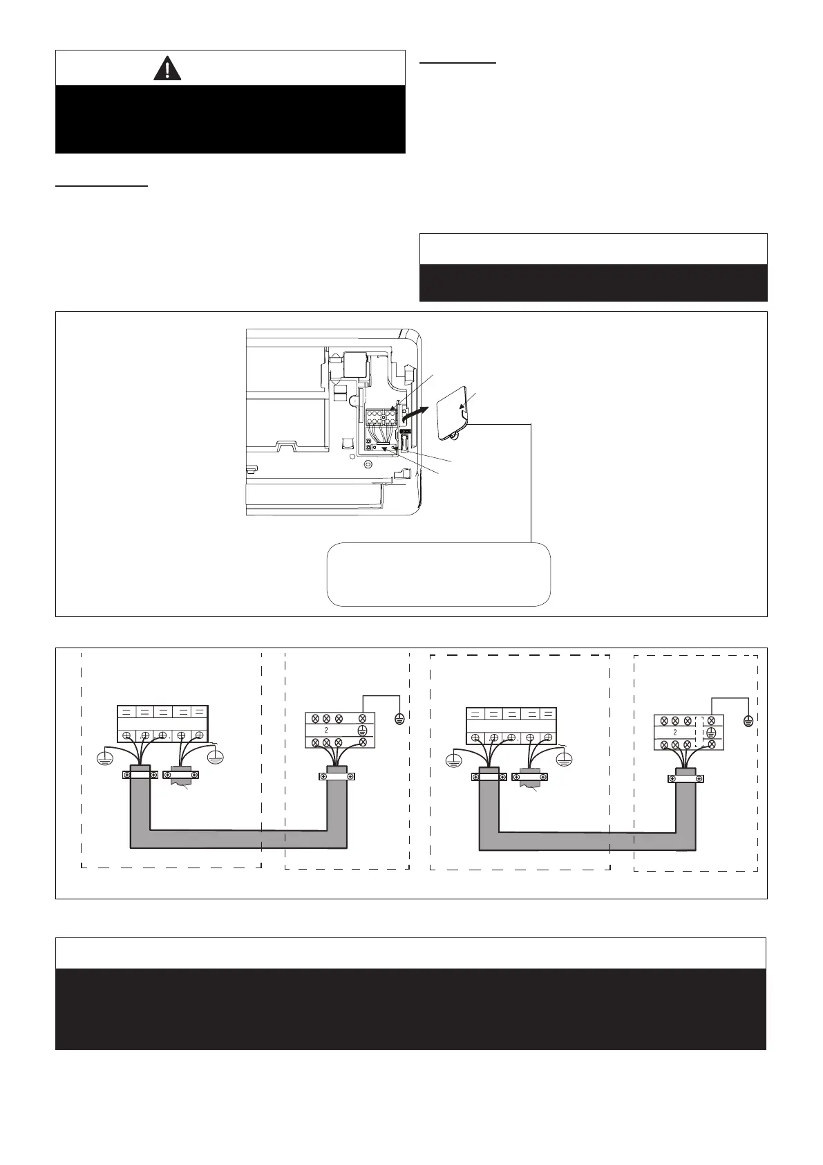
Terminal block
Terminal Block
Cover
Screw
Cable Clamp
The wiring diagram is located
on the inside of the indoor unit’s
terminal block cover.
Figure 27. Indoor Unit Terminal Block
208/230V Outdoor Unit
Terminal Block
From Power
Supply
Terminal Block
208/230V Indoor Unit
Outdoor Unit Indoor Unit
3
2
L1
L2
1
Y/G
1
3
Y/G
Y/G
115VAC Outdoor Unit
Terminal Block
From Power
Supply
Terminal Block
115VAC Indoor Unit
Outdoor Unit Indoor Unit
3
2
L
N
1
Y/G
1
3
Y/G
Y/G
*
*
18 and 24K
unit has
five terminal
sets.
Figure 28. Single Zone Wiring
IMPORTANT
This unit must be properly grounded and protected by a circuit breaker. The ground wire for the unit must not be
connected to a gas or water pipe, a lightning conductor or a telephone ground wire.
Do not connect power wires to the outdoor unit until all other wiring and piping connections have been completed.
Do not install the unit near a lighting appliance that includes a ballast. The ballast may affect remote control operation.

 Loading...