14
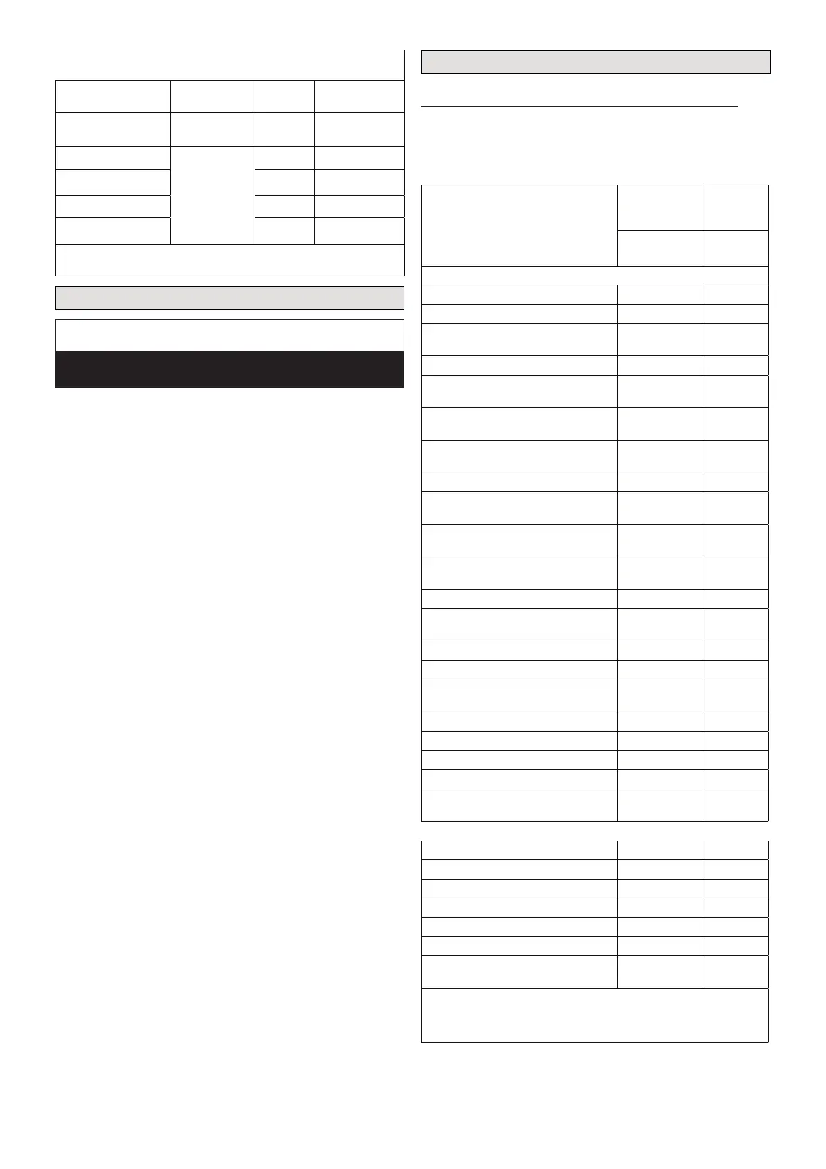
Table 7. Single Zone Installation Electrical
Outdoor Unit Model
Voltage/Phase,
Hz
MCA Max Fuse
MCB012S4S-1L 115 / 1 / 60 18 30
MCB009S4S-1P
208/230 / 1 / 60
11 15
MCB012S4S-1P 11 15
MCB018S4S-1P 16 20
MCB024S4S-1P 16 20
MCA = Minimum Circuit Amps
Unit Start-Up
IMPORTANT
Units should be energized 24 hours before unit start-up
to prevent compressor damage as a result of slugging.
1. Inspect all factory- and eld-installed wiring for loose
connections.
2. Verify that the manifold gauge set is connected.
3. Add additional refrigerant charge if required before
opening valves and while system is still under a
vacuum.
4. Open the liquid and suction line service valves to
release the refrigerant charge contained in outdoor
unit into the system.
5. Replace the stem caps and tighten to the value listed
in “Table 1. Torque Requirements” on page 6.
6. Check voltage supply at the outdoor unit terminal strip.
The voltage must be within the range listed on the
unit’s nameplate. If not, do not start the equipment
until you have consulted with the power company and
the voltage condition has been corrected.
7. Refer to the included user guide to operate the system
using the provided remote control.
8. Visually check for binding of both indoor and outdoor
fans.
Service Information
Indoor Unit Alert Codes and Outdoor Unit LED
The following codes are display on the indoor unit LED on
the outdoor unit.
Table 8. Indoor Display Alert and Status Codes and
Outdoor Unit LED
Unit Error Codes
Outdoor Unit
Main Control
Board
Indoor
Unit
Display
MCB MWCB
System Error Codes
Indoor unit EEPROM error n/a EH 00
Indoor unit EEPROM parameter error n/a EH 0A
Communication error between indoor
unit and outdoor units
n/a EL 01
Indoor fan speed error (DC motor) n/a EH 03
Indoor room temperature sensor
error (T1)
n/a EH 60
Indoor coil temperature sensor error
(T2)
n/a EH 61
Refrigerant leakage detection
(Cooling mode only)
n/a EL 0C
Outdoor current overload protection n/a PC 08
Outdoor ambient temperature sensor
error (T4)
n/a EC 53
Outdoor coil temperature sensor
error (T3)
n/a EC 52
Compressor discharge temperature
sensor error (T5)
n/a EC 54
Outdoor unit EEPROM error n/a EC 51
Outdoor unit fan speed error (DC fan
motor)
n/a EC 07
Inverter module IPM error n/a PC 00
High or Low voltage protection n/a PC 01
Outdoor low ambient temperature
protection
n/a PC 0L
Compressor drive error n/a PC 04
Standby SLOW FLASH n/a
Normal operation LIT n/a
Outdoor unit error FAST FLASH n/a
Communication error between main
control board and display board
n/a EH 0b
Operational Status Codes
Force Cooling n/a FC
Remote or Wired controller Lock n/a LL
Active clean n/a CL
Time On n/a On
Time Off n/a OF
Remote On/Off n/a CP
ECO mode n/a
On display
3 seconds
Outdoor Unit LED:
Slow ash: Flashing at 1Hz
Fast ash: Flashing at 2Hz

 Loading...