Page 31
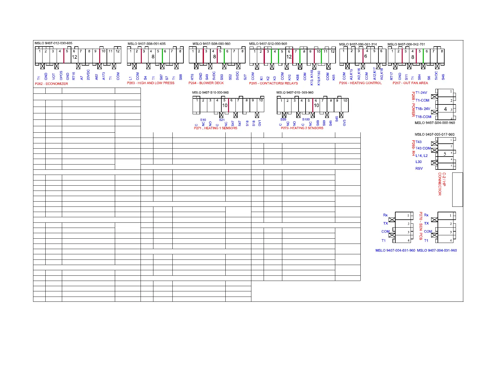
Table 9. M2 board connections diagram
Pin# Label Description Type
10
P262 Economozer control
1 R 24VAC Power 24 VAC
2 GND Digital Ground 24 VAC COM
3 VOT Damper Control 2−10 VDC AO
4 DPOS Damper Position Feedback 2−10 VDC AI
5 GND Digital Ground
RES 0−5 VDC
6 RT16+ Return Air Temp 7 K68 Relay Outdoor Fan 2 24 VAC DO 5 RSV Reserved 24 VAC DI
P270 DISPLAY PCB
7 A7 S Outdoor Enthalpy Sensor 4−20 mA AI 8 COM 24 VAC Common COM P270 Sensor Board
8 20 VDC 10 Volts DC Power 20 VDC 9 K13 Relay Combustion Air Blower 1 24 VAC DO 1 + RS−485 Communication BUS
9 A62 S Indoor Enthalpy Sensor 4−20 mA AI 10 K19 Relay Combustion Air Blower 2 24 VAC DO 2 − RS−485 Communication BUS
10 A173 Smoke Detector 24 V DI 11 COM 24 VAC Common COM 3 COM 24 VAC Common Transformer 1 24 VAC COM
11 T1 Smoke Detector 24V
24 VAC
Power
12 K65 Relay Exhaust Fan 24 VAC DO 5 T1 24 VAC Transformer 1 24 VAC
12 COM Smoke Detector 24 Common P266 Heating Control P271 Heating 1 Safety
P263 High $ Low Pressure 1 COM 24 VAC Common 24 VAC COM 1 S10−C Primary Limit Burner 1 C
SW 24 VAC
1 L1 Reversing Valve 24 VAC DO 2 A3, K15 Heat 1, Electric Heat 1 24 VAC DO 2 S10−NC Primary Limit Burner 1 NC
2 COM 24 VAC Common 24 VAC COM 3 W2, K16 Heat 2, Electric Heat 2 24 VAC DO 3 S10−NC Primary Limit Burner 1 NO
3 S4 High Pressure Compressor 1 SW 24 VAC 4 COM 24 VAC Common 24 VAC COM 4 S21−C Secondary Limit Burner 1 C
SW 24 VAC
4 T1 24VAC Power 24 VAC 5 A12, K17 Heat 3, Electric Heat 3 24 VAC DO 5 S21−NC Secondary Limit Burner 1 NC
5 S87 Low Pressure Compressor 1 NC SW 24 VAC 6 W2, K15 Heat 4, Electric Heat 4 24 VAC DO 6 S47 Rollout Switch Burner 1 C
SW 24 VAC
6 S7 High Pressure Compressor 2 SW 24 VAC P267 Outdoor Fan Area 7 S47 Rollout Switch Burner 1 NC
7 T1 24VAC Power 24 VAC 1 RT17 Outdoor Air Temp
RES 0−5 VDC
8 S18 Cab Proof Switch 1
SW 24 VAC
8 S88 Low Pressure Compressor 2 SW 24 VAC 2 GND Digital Ground 9 S18 Cab Proof Switch 1
P264 Blower Deck Area 3 S11 Low Pressure Fan 1 SW 24 VAC 10 GV1 Gas Valve Sense 1 24 VAC DI
1 RT6 Discharge Air Temp
RES 0−5 VDC
4 R 24 VAC 24 VAC DO P272 Heating 2 Safety
2 GND Digital Ground 5 S84 Low Pressure Fan 2 SW 24 VAC 1 S99−C Primary Limit Burner 2 C
SW 24 VAC
3 S49 Freezestat 1 (NC) SW 5 VDC 6 S6 Defrost Temp SW 5 VDC 2 S99−NC Primary Limit Burner 2 NC
4 VSS 5VDC 5 VDC 7 VSS 5VDC 5 VDC 3 S99−NO Primary Limit Burner 2 NO
5 S50 Freezestat 2 (NC) SW 5 VDC 8 S46 Defrost Pressure 1 SW 5 VdC 4 S100−C Secondary Limit Burner 2 C
SW 24 VAC
6 S52 Air Flow Switch (NO) SW 5 VDC P268 Power 5 S100−NC Secondary Limit Burner 2 NC
7 VSS 5VDC 5 VDC 1 T1−1 24 VAC Power Transformer 1 24 VAC 6 S69 Rollout Switch Burner 2 C
SW 24 VAC
8 S27 Dirty Filter Switch (NO) SW 5 VDC 2 T1−COM 24 VAC Common Transformer 1 24 VAC COM 7 S69 Rollout Switch Burner 2 NC
P265 Contactors / Relays 3 T18−1 24 VAC Power Transformer 1 24 VAC 8 S45 Cab Proof Switch 2
SW 24 VAC
1 COM 24 VAC Common 24 VAC COM 4 T18−COM 24 VAC Common 24 VAC COM 9 S45 Cab Proof Switch 2
2 K1 Contactor Compressor 1 24 VAC DO P269 Reheat − Humiditrol 10 GV3 Gas Valve Sense 2 24 VAC DI
3 K2 Contactor Compressorr 2 24 VAC DO 1 T43 24 VAC Power 24 VAC
4 K3 Contactor Blower 24 VAC DO 2 T43 24 VAC Common 24 VAC COM
5 COM 24 VAC Commo 24 VAC COM 3 L14 Reheat Solenoid 1 24 VAC DO
6 K10 Relay Outdoor Fan 1 24 VAC DO 4 L30 Reheat Solenoid 2 24 VAC DO

 Loading...


