Page 32
Quick Start Guide
CAUTION
Check rooftop unit electrical power for proper voltage and phasing. Check gas train components.
1. Turn on unit, correct alarm issues as necessary.
2. Follow GUIDED SETUP menu to properly configure unit (see Page 8).
3. Be sure unit is in normal operating mode as seen in display (COOLING, HEATING, IDLE, etc).
4. Conduct unit startup to verify operation under SERVICE−> TEST menu (see Page 11).
5. Insert USB memory stick into display cover to verify service and collect unit information.
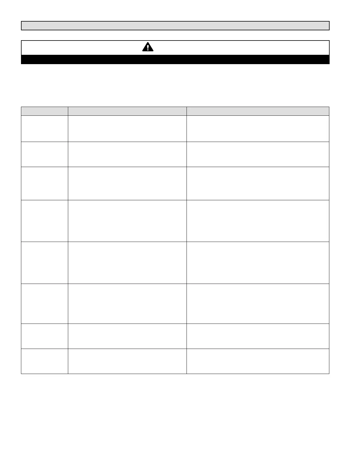
Control Mode Menu Setup Needed Tips
THERMOSTAT
(Factory set for 2 stage thermostat)
Check 2 AMP fuse if wiring error.
Check LEDs for signals.
Check ground switch position.
LOCAL MODE
Change default backup setpoints; see
SETTINGS −> CONTROL −> LOCAL
(Page 15).
Give unit time to startup, error codes 74 and 93
are expected.
Humidity control requires sensor or error code 76
MSAV
Change motor torque; see
SETTINGS −> CONTROL −> LOCAL
(Page 16).
Use LENNOX MSAV trained technician.
Final motor CFM needs to be set by Test and
Balance technician
Blower charts are located in unit EHB.
BACnet
Select control mode; see
SETTINGS −> CONTROL −> BACNET
(Page 16).
Setup information to be verified with integrator.
Follow wiring instructions including network
termination
Remember to set MAC address 0−127
Expert level BACnet service manual available.
LonTalk
Select control mode; see
SETTINGS−> CONTROL −> LONTALK
(Page 16).
Setup information to be verified with integrator.
Follow wiring instructions including network
termination
XIF file available. Neuron ID on sticker.
Expert level LonTalk service manual available.
L Connection
Select control mode; see
SETTINGS −> CONTROL −> LCONN
(Page 15).
Follow wiring instructions including network
termination
Comfort Sensors are 24 VAC polarity sensitive.
All network devices need to be correctly
addressed
Damper
Select control mode; see
SETTINGS −> SETPOINTS −> DAMPER
(Page 14).
Verify damper minimum positions
Refer to Economizer section of manual for more
detail
Reheat
Select sensor type; see
SETTINGS −> CONTROL −> REHEAT
(Page 16).
Two possible connections, SENSOR and
HUMIDISTAT
Analog sensor wiring is polarity sensitive
For Lennox Service Support 1−800−4LENNOX

 Loading...


