Page 6
DISPLAY Interface DISPLAY
The display shows operating mode if in normal operation.
Alarm, status, calls and plugging in the USB will interrupt
the display. Alarm messages will stay displayed until cor-
rected or silenced using the local menu.
ALARM Example ˘ MODE message COOLING" is dis-
playing when a smoke alarm occurs; then ALARM (XX)
SMOKE A173" displays until cleared. You must clear all
alarms and status to see normal MODE message. Strike 3
alarms will say ALARM(XX) STRIKE 3 COMP1 HIGH
PRESS S4" after the alarm message.
USB ˘ normal MODE message is displayed when USB is
plugged in; message examples:
WRITING USB"
WRITING ALARM/STATUS LOG"
USB COMPLETE"
Normal Mode Messages
The format of the message is mode and setpoint (see table
3).
Table 3. Possible MODE messages
COMP LOAD
SHEDDING
Unit is running at lower power capacity
COOLING Cool demand present; unit is cooling
DEHUMIDIFICATION Unit is dehumidifying
FAN ONLY Fan only
FREE COOLING No compressor cooling
FRESH AIR COOL Cool ventilation air to neutral value
FRESH AIR HEAT Heat ventilation air to neutral value
HEATING Heat demand present; unit is heating
HVAC OFF No heat, cool, ventilation allowed
IDLE Demand satisfied; blower off
LOW AMBIENT
LOCKOUT
Outdoor air is too cold to allow fans to
run
MORNING WARMUP Outdoor air damper closed
M2 FAILED TO
RESPOND
Display is missing messages from M2
M2 RESET M2 controller is resetting
OFF ON ALARM Unit is off due presence of alarm
ONE BLINKING LED Bootloader mode
PRE−COOL
No compressor allowed when free cool-
ing
PREINSTALL Must follow installation menus
RESTARTING.. Only displayed at power−up
SMOKE Smoke input detected
TEST Network has unit in test mode
Unit Operation
This section describes the display and control buttons,
how to configure the unit, and how to read stored configu-
ration data, status, and alarms.
The M2 unit controller is an input and output junction
point. If in the thermostat mode, thermostat inputs at
P297 result in an output to unit components (see table 8
on Page 30). If the heartbeat LED is not flashing, see
table 1 (Page 3) for heartbeat operation. If the display
shows an alarm, refer to table 7 (Page 22) for more infor-
mation. If the thermostat input indicating lights are not
responding appropriately, check the thermostat or a
DDC control acting as thermostat inputs into P297.
Basic cooling and heating functions may be energized to
test major unit components by using the M2 unit controller
testing function or by using jumper wires on the Field Wir-
ing Termination plug P297.
To access the other three columns, first press and then
use to scroll between SERVICE, DATA, AND SET-
TINGS. Next, press to open the SERVICE (or DATA or
SETTINGS) menu. Use until desired item is dis-
played.
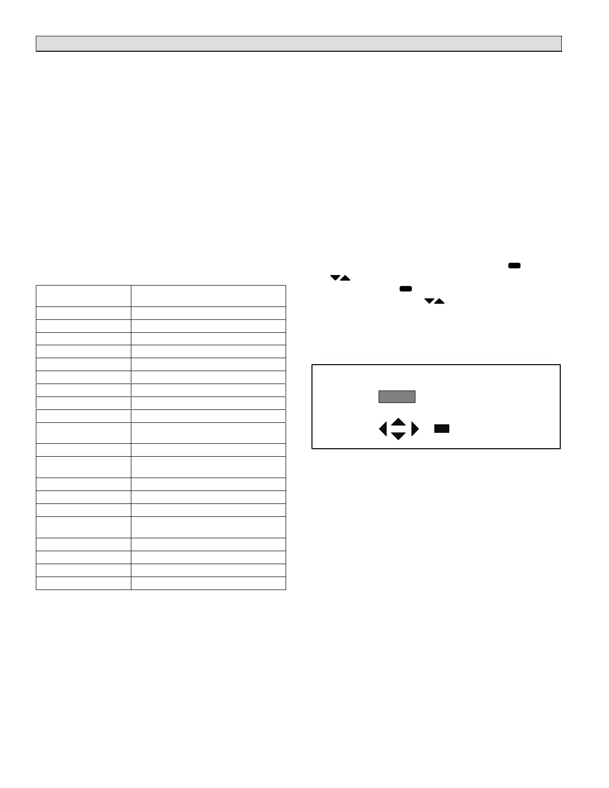
Alarms
Figure 3 shows a typical alarm and how the message will
scroll.
ALARM(xx) SMOKE DETECTED.
DISPLAY
WINDOW
LEFT SCROLLING
MESSAGE
(To SILENCE an alarm,
press any of these buttons.)
Figure 3. Alarm Code Readout Example
SILENCE − to silence an alarm, press any of the control
buttons while the alarm is displayed.

 Loading...


