24
XC20
IMPORTANT
Use a thermocouple or thermistor electronic vacuum
gauge that is calibrated in microns. Use an instrument
capable of accurately measuring down to 50 microns.
WARNING
Danger of Equipment Damage. Avoid deep vacuum
operation. Do not use compressors to evacuate a
system. Extremely low vacuums can cause internal
arcing and compressor failure. Damage caused by
deep vacuum operation will void warranty.
Evacuating the system of non-condensables is critical for
proper operation of the unit. Non-condensables are
defined as any gas that will not condense under temperat
ures and pressures present during operation of an air
conditioning system. Non-condensables combine with re
frigerant to produce substances that corrode copper piping
and compressor parts.
Electrical
In the U.S.A., wiring must conform with current local codes
and the current National Electric Code (NEC). In Canada,
wiring must conform with current local codes and the current
Canadian Electrical Code (CEC).
Refer to the furnace or air handler installation instructions
for additional wiring application diagrams. Refer to unit
nameplate for minimum circuit ampacity and maximum
over-current protection size.
24VAC TRANSFORMER
Use the transformer provided with the furnace or air hand
ler for low‐voltage control power (24VAC - 40 VA
minimum).
Load Shedding
Utility Load Shedding Mode ACTIVATED
(Utility Cycled Unit OFF) – The normally closed set of
contacts in the utility load shedding control receiver OPEN.
This removes 24VAC from the coil of the field-provided re
lay (catalog # 69J79). The relay contacts close (terminal 7
to terminal 2), completing the circuit between terminals R
and L on the outdoor control. The 24VAC input to terminal L
activates the load-shedding mode in the outdoor control,
cycling the outdoor unit OFF. The 7-Segment display on
the outdoor control displays a load shedding alert code
(E600) and an alert appears on the display of the iComfort
Wi-Fi
®
thermostat. The customer receives email notifica
tions when the alert occurs, if the option to receive
notifications is selected.
Utility Load-Shedding Mode DEACTIVATED
(Normal Equipment Operation) – When load shedding
mode is not required, the contacts in the utility load control
receiver are closed. This provides 24VAC to the coil of the
field-provided relay (catalog # 69J79).The relay contacts
OPEN (terminal 7 to terminal 2) removing 24VAC from the
L terminal on the outdoor control. This deactivates the
load-shedding mode in the outdoor control. The outdoor
unit returns to normal operation and alert code clears once
load-shedding mode is deactivated.
For more information, see the Load-Shedding Feature Wir
ing Diagram on page 47.
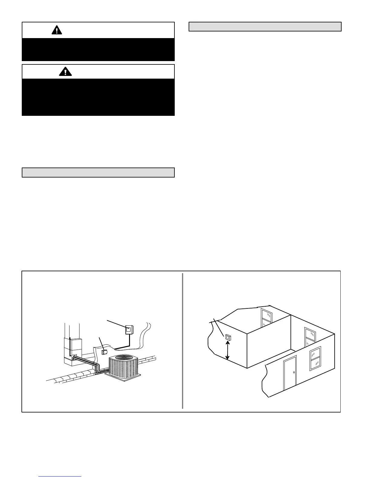
REFER TO THE UNIT NAMEPLATE FOR MINIMUM CIRCUIT AMPACITY,
AND MAXIMUM FUSE OR CIRCUIT BREAKER (HACR PER NEC).
INSTALL POWER WIRING AND PROPERLY SIZED DISCONNECT
SWITCH.
NOTE - UNITS ARE APPROVED FOR USE ONLY WITH COPPER
CONDUCTORS. GROUND UNIT AT DISCONNECT SWITCH OR TO AN
EARTH GROUND.
SIZE CIRCUIT AND INSTALL DISCONNECT
SWITCH
1
NOTE - 24VAC, CLASS II CIRCUIT CONNECTIONS ARE MADE IN THE CON
TROL BOX.
INSTALL ROOM THERMOSTAT (ORDERED SEPARATELY) ON AN
INSIDE WALL, APPROXIMATELY IN THE CENTER OF THE
CONDITIONED AREA AND 5 FEET (1.5M) FROM THE FLOOR. IT
SHOULD NOT BE INSTALLED ON AN OUTSIDE WALL OR WHERE IT
CAN BE AFFECTED BY SUNLIGHT OR DRAFTS.
THERMOSTAT
5 FEET
(1.5M)
INSTALL THERMOSTAT
2
DISCONNECT
SWITCH
MAIN FUSE BOX/
BREAKER PANEL
Figure 12. Electrical Installation

 Loading...