30
XC20
III. SYSTEM OPERATION AND SERVICE
7-Segment Alert and System Status Codes
Alert codes are displayed using the 7-segment display loc
ated on the outdoor control.
NOTE - System fault and lockout codes take precedence
over system status codes (cooling, heating operating per
centages or defrost/dehumidification).
The 7-segment will display an abnormal condition (error
code) when detected in the system. A list of the codes are
shown in table 6.
RESETTING ALERT CODES
Alert codes can be reset manually or automatically:
1. Manual Reset
Manual reset can be achieved by one of the following
methods:
• Disconnecting R wire from the outdoor control R
terminal.
• Turning the indoor unit off and back on again
After power up, all currently displayed codes are
cleared.
2. Automatic Reset
After an alert is detected, the outdoor control continues
to monitor the unit's system and compressor opera
tions. When/if conditions return to normal, the alert
code is turned off automatically.
NOTE - Error codes can be recalled by following in
formation shown in the table on page 37.
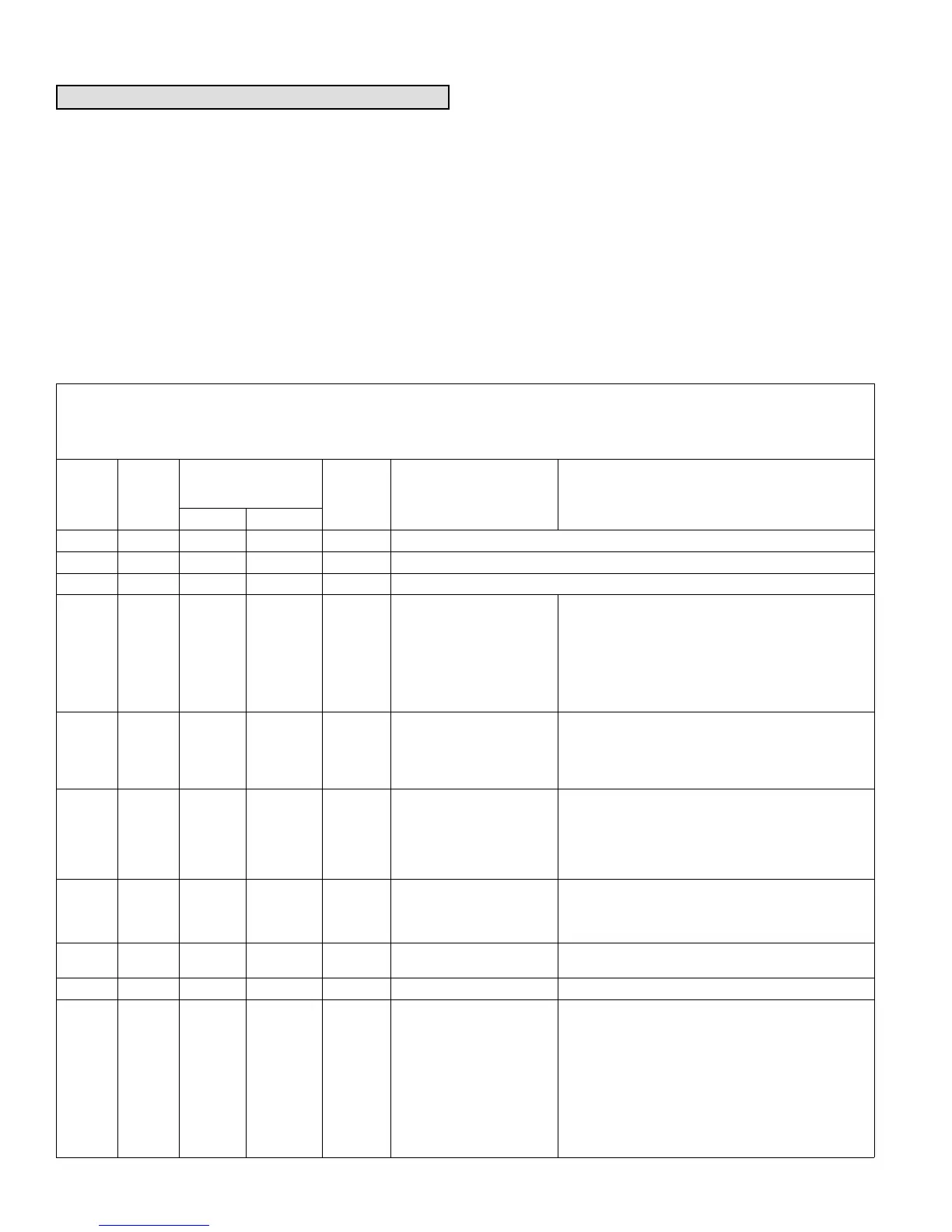
Table 6. Outdoor Control 7-Segment Display Alert Codes and Inverter LED Flash Codes
NOTE - System fault and lockout codes take precedence over system status codes (cooling, heating operating percentages or defrost/dehumidification).
Only the latest active fault or lockout codes are displayed (if present). If no fault or lockout codes are active, then system status codes are displayed. Alert
codes are also displayed on the iComfort Wi-Fi
®
or iComfort
®
S30 thermostat.
Alert
Codes
Inverter
Code
Inverter LED Flash
Code (number of
flashes)
Priority Alarm Description Possible Causes and Clearing Alarm
Red LED Green LED
N/A N/A ON OFF N/A XC/XP 20-024 and -036 only: Indicates inverter is operating normally.
N/A N/A ON ON N/A XC/XP 20-048 and -060 only: Indicates inverter is operating normally.
N/A N/A OFF OFF N/A Indicates inverter is NOT energized.
E 105 N/A N/A N/A Moderate
The outdoor control has
lost communication with
either the thermostat or in
door unit.
Equipment is unable to communicate. Indicates nu
merous message errors. In most cases errors are re
lated to electrical noise. Make sure high voltage power
is separated from RSBus. Check for miswired and/or
loose connections between the stat, indoor unit and
outdoor unit. Check for a high voltage source of noise
close to the system. Fault clears after communication
is restored.
E 120 N/A N/A N/A Moderate
There is a delay in the out
door unit responding to the
system.
Typically, this alarm/code does not cause any issues
and clears on its own. The alarm/code is usually
caused by a delay in the outdoor unit responding to the
thermostat. Check all wiring connections. Cleared
after unresponsive device responds to any inquiry.
E 124 N/A N/A N/A Critical
The iComfort WiFi
®
or
iComfort
®
S30 thermostat
has lost communication
with the outdoor unit for
more than 3 minutes.
Equipment lost communication with the thermostat.
Check the wiring connections and resistance, then
cycle the system power. This alarm stops all associ
ated HVAC operations and waits for a signal from the
non-communicating unit. The alarm / fault clears after
communication is reestablished.
E 125 N/A N/A N/A Critical
There is a hardware prob
lem with the outdoor con
trol.
There is a control hardware problem. Replace the out
door control if the problem prevents operation and is
persistent. The alarm / fault is cleared 300 seconds after
the fault recovers.
E 131 N/A N/A N/A Critical
The outdoor unit control
parameters are corrupted.
Reconfigure the system. Replace the control if heating or
cooling is not available.
E 132 N/A N/A N/A Critical Internal software error. Replace outdoor control.
E 180 N/A N/A N/A Critical
The outdoor unit ambient
temperature sensor has
malfunctioned. As a result
the outdoor unit control will
not perform low ambient
cooling.
Valid temperature reading is lost during normal opera
tion and after outdoor control recognized sensors.
Compare outdoor sensor resistance to temperature/
resistance charts in unit installation instructions. Re
place sensor pack if necessary. At the beginning of
(any) configuration, furnace or airhandler control de
tects the presence of the sensor(s). If detected (reading
in range), appropriate feature is shown in the iComfort
WiFi
®
or iComfort
®
S30 thermostat About screen. The
alarm / fault clears upon configuration, or when normal
values are sensed.

 Loading...