70
XC20
ERROR CCOCODES:
Table 16. Outdoor Control 7-Segment Display Alert Codes - Outdoor Control Errors
NOTE - System fault and lockout codes take precedence over system status codes (cooling, heating operating percentages
or defrost/dehumidification). Only the latest active fault or lockout codes are displayed (if present). If no fault or lockout codes
are active, then system status codes are displayed. Alert codes are also displayed on the iComfort Wi-Fi
®
or iComfort
®
S30
thermostat.
Alert
Codes
Priority Alarm Description Possible Causes and Clearing Alarm
E 180 Critical
The iComfort Wi-Fi
®
thermostat has
found a problem with the outdoor
unit's ambient temperature sensor.
During normal operation, after the outdoor control recognizes sensors, the alarm will
be sent only if valid temperature reading is lost. Compare outdoor sensor resistance to
temperature/resistance charts in unit installation instructions. Replace sensor pack if
necessary. At the beginning of (any) configuration, furnace or air-handler control will
detect the presence of the sensor(s). If detected (reading in range), appropriate
feature will be set as 'installed' and shown in the iComfort Wi-Fi
®
thermostat 'About'
screen. The alarm / fault will clear upon configuration, or sensing normal values.
E 416
Moderate /
Critical
The outdoor coil sensor is either
open, short-circuited or the
temperature is out of sensor range.
As a result the outdoor unit control
will not perform defrost.
Coil sensor is detected as open or shorted, or temperature is out of coil sensor range.
Outdoor unit control will not perform demand or time/temperature defrost operation.
System will still heat or cool. Check the resistance of the coil sensor and compare to
temperature resistance chart. Replace coil sensor if needed. The alarm clears when
outdoor unit control detects proper coil sensor readings or after a power reset.
E 424 Moderate Faulty outdoor liquid line sensor Sensor is open or shorted. Replace the sensor.
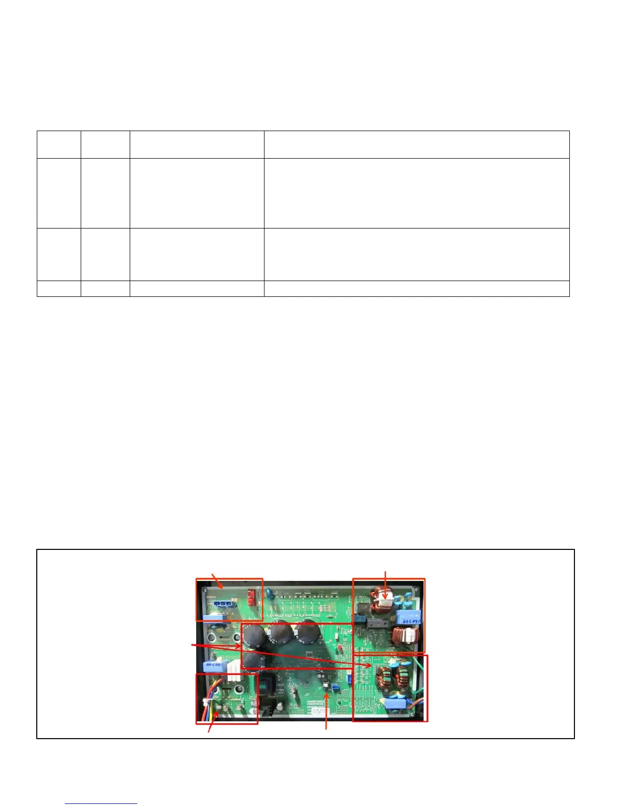
DC Inverter Control Operation, Checkout, Status / Error Codes
OPERATION OF COMPONENTS:
Electromagnetic compatibility circuit (EMC): EMC ensures the correct operation of different equipment items which use or
respond to electromagnetic phenomena. It also helps to negate the effects of interference. NOTE - The 2- and 3-ton inverter
has an EMC builtin. The 4- and 5-ton units have an external inverter.
CONVERTER:
Converts AC (alternating current) to DC (direct current).
POWER FACTOR CORRECTION (PFC) CIRCUIT:
The PFC module is an integrated part of the outdoor inverter that monitors the DC bus for high, low and abnormal voltage
conditions. If any of these conditions are detected, the PFC function and compressor will stop.
INTELLIGENT (INVERTER) POWER MODULE (IPM):
The IPM converts DC power into AC power. The control method is known as pulse width modulation (PWM). This means the
DC is switched on and off very quickly (chopped) by the transistor switches to make simulated AC at required frequency and
voltage.
COMMUNICATION CONTROL CIRCUIT:
Receives and sends message between the inverter and the outdoor control.
Intelligent Power Module
Converter
Electromagnetic Compatibility Circuits
Power Factor Correction Circuit
Communication Control
Figure 51. 2- and 3-Ton Unit Inverter

 Loading...