47
XC25
Unit Sequence of Operation
The following figures illustrated the overall unit sequence of operation along with the operation of various pressure switches
and temperature sensors. The figures also illustration the use of the compressor anti-short cycle function in relations to unit
Status, Fault and lock out LED Codes system operations interaction.
Yes
No
Yes
No
Room thermostat is sending a cooling percent
age of maximum capacity demand to the main
control board in the outdoor unit.
All switches closed
and sensors in operat
ing range.
Check for status or
fault codes in the
outdoor control or
room thermostat.
(NOTE - Refer to low
pressure and high
pressure switch flow
charts for sequence
of operation.
1. View the AIR CONDITIONING screen
for current compressor frequency in
hertz.
2. View the OUTDOOR CONTROL
7-Segment display to read the RPM of
the outdoor fan motor.
3. View the AIR HANDLER screen for
actual CFM of the indoor blower
motor.
From idle mode
Outdoor Control
1. Sends a demand to the compressor
inverter to start and run the
compressor up to the requested
pumping capacity (Frequency in
hertz).
2. Outputs a DC voltage on the DAN
PWM and COM terminals to start
and run the outdoor fan motor at the
demand RPM.
3. Sends a communication signal into
the indoor unit to start and run the
supply fan motor at the demand air
volume (CFM).
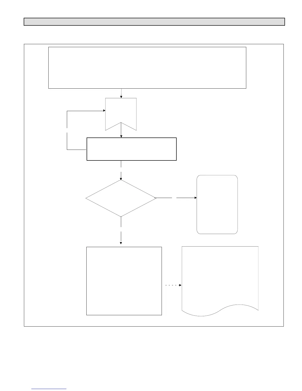
On 24 VAC power-up or outdoor reset, the outdoor control shall perform the following tasks:
1. Start the anti-short cycle 3-minute delay in the outdoor control.
2. Check status of the temperature sensor and pressure devices.
3. If the outdoor control does not detect any error codes, outdoor control sends 24 volts out on the
CNTCTR terminals to pull in the contactor coil. (Note - These checks take about 60 seconds).
4. The contactor contacts pull IN and main power is applied to the compressor inverter.
Diagnostic Screen
Figure 28. 24 Volt Power-Up or Outdoor Reset

 Loading...