69
XC25
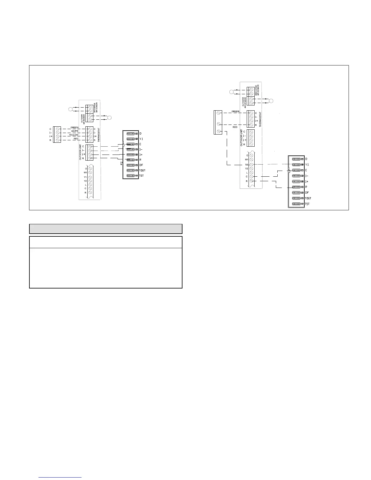
Emergency 24VAC System Operation
The Y terminal located on the outdoor control allows the outdoor unit to be cycled ON and OFF using 24VAC inputs. The
outdoor unit will operate at 100% capacity in this configuration.
The following wiring diagrams display the wiring changes needed to switch a full communicating system to a non-communic
ating system with the XC25 running in emergency mode (24VAC inputs to outdoor unit).
Emergency 24VAC
Communicating Air
Handler or
Furnance
24VAC Thermostat
Thermostat,
Communicating Air Handler and XC25
RSBus
Communicating Air
Handler or
Furnance
NOTE 1 and 2
(Non−Communicating Mode)
C
Y
R
XC25 UNIT
XC25 UNIT
NOTES:
1. Move one wire on both
indoor and outdoor controls
from terminals i+ to Y1 for
24VAC operation on air
conditioner and indoor unit.
2. Disconnect the i- wire from
terminal strip and tape.
3. Do not disconnect wires
form the XC25 R and C
terminals, both are required.
NOTE 3
IComfort Wi-Fi
IComfort
®
Wi-Fi
THERMOSTAT
Figure 54. Emergency 24VAC System Operation
System Refrigerant
IMPORTANT !
The system must be operating at full capacity during
charging. Increase (heat) or decrease (cooling) the
thermostat setting by 5°F to create system demand.
Confirm outdoor unit running capacity on the
display on the outdoor control. Value should be
100%.
This section outlines the procedures to:
1. Connect a gauge set for testing and charging as illustrated in fig
ure 55.
2. Check and adjust indoor airflow as described in figure 56.
3. Add or remove refrigerant using the weigh-in method shown in
figure 57.
4. Verify the charge using the subcooling method described in fig
ure 58.
IMPORTANT: Unit must be operating at 100% input to be charged
properly.
ADDING OR REMOVING REFRIGERANT
This system uses HFC-410A refrigerant which operates at much
higher pressures than HCFC-22. The pre-installed liquid line filter
drier is approved for use with HFC-410A only. Do not replace it with
components designed for use with HCFC-22.
INDOOR AIRFLOW CHECK
Check airflow using the Delta-T (DT) process using the illustration in
figure 56.
The diagnostic screen on the thermostat or outdoor control 7-seg
ment display shows indoor and outdoor motor CFMs or RPMs.

 Loading...