Hardware Maintenance Manual
38
1090 System board
For access, remove these FRUs in order:
• “1010 Card tray” on page 24
• “1020 Battery cover” on page 25
• “1030 Battery pack” on page 26
• “1040 Speakers” on page 28
• “1050 Fingerprint module and POGOPIN FPC” on page 31
• “1060 SIM card slot and vibrator module” on page 33
• “1070 Antenna” on page 35
• “1080 LCD module FPC” on page 37
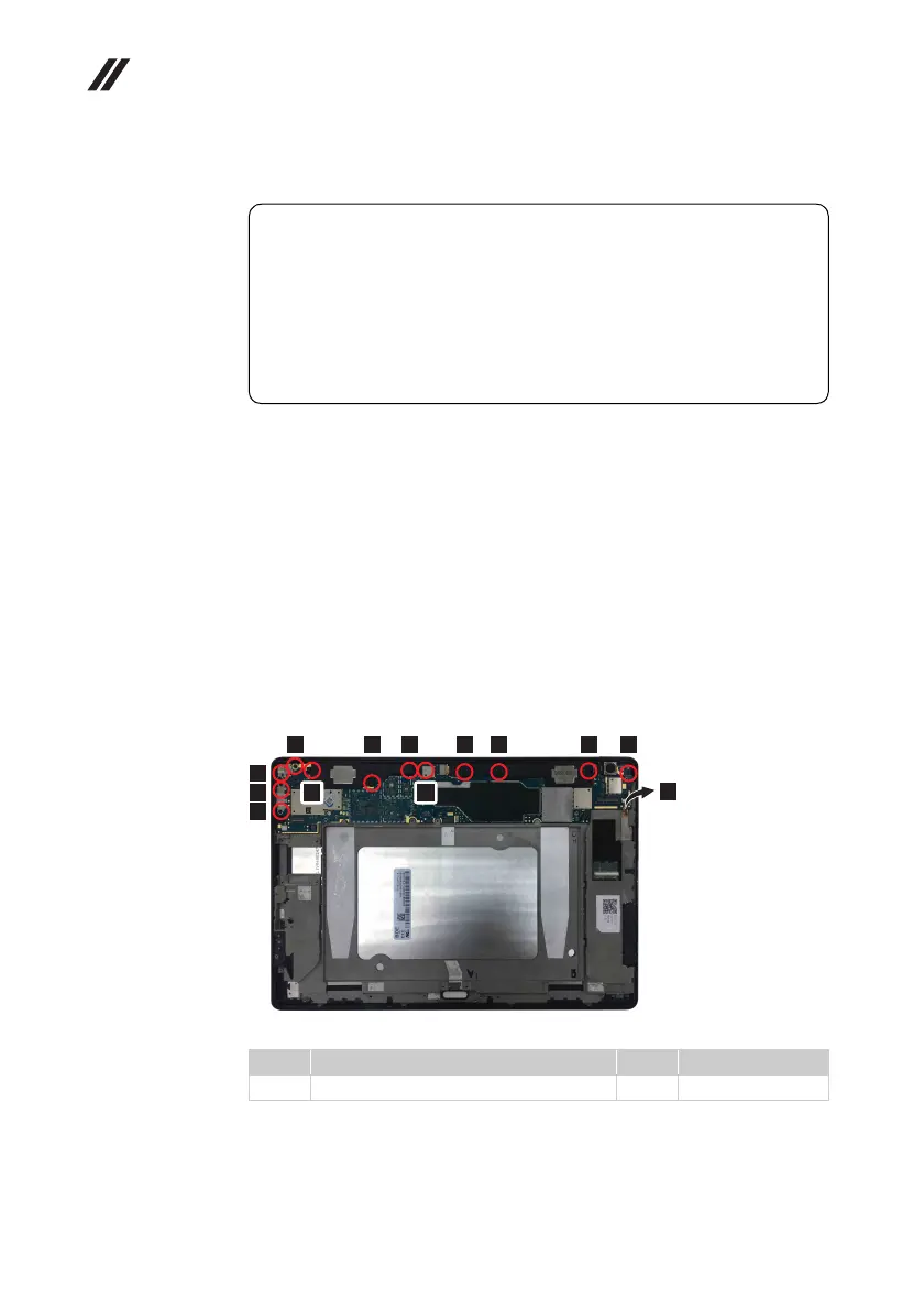
Figure 9. Removal steps of system board
Detach the side key connector , and remove the screws , .
Lenovo TB-X705F
Step Screw (quantity) Color Torque
M1.4 × 2.5 mm, Phillips head(12) Black Appr. 0.6 kgf·cm
Important notices for handling the system board:
When handling the system board, bear the following in mind.
• Be careful not to drop the system board on a bench top that has a hard
surface, such as metal, wood, or composite.
• Avoid rough handling of any kind.
• In the whole process, make sure not to drop or stack the system board.
• If you put a system board down, make sure to put it only on a padded
surface such as an ESD mat or conductive corrugated material.
a b
1
2
2
2
2 2 2 2 2 2 2
2 2
a
 Loading...