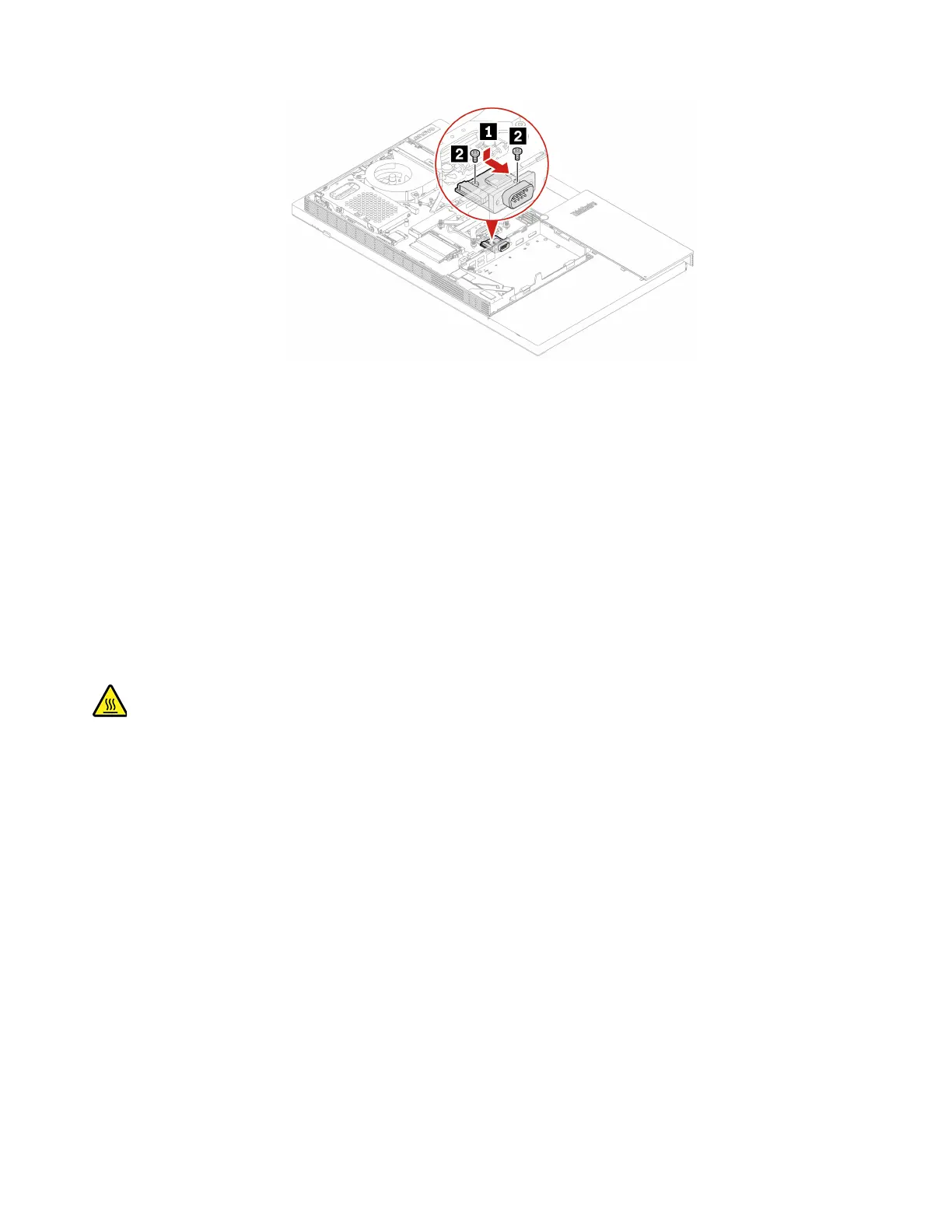
Figure 88. Installing the serial connector module
10. Connect the new serial connector cable to the system board.
11. Reinstall the removed parts.
12. Place the computer in an upright position.
13. If a locking device is available, use it to lock the computer.
14. Reconnect the external cables and power cords to the corresponding connectors on the computer.
Cable cover
Prerequisite
Before you start, read Chapter 1 “Important safety information” on page 1 and print the following
instructions.
Before you open the cable cover door, turn off the computer and wait several minutes until the computer is
cool.
Replacement procedure
1. Remove the computer stand. See “Computer stand” on page 61.
2. Remove the rear cover. See “Rear cover” on page 65.
3. Remove the optical drive. See “Optical drive” on page 66.
4. Remove the optical drive holder. See “Optical drive holder” on page 69.
5. Remove the system board shield. See “System board shield” on page 71.
6. Remove the VESA mount bracket cover. See “VESA mount bracket cover” on page 74.
7. Remove the VESA mount bracket. See “VESA mount bracket” on page 76.
8. Remove the serial connector module. See “Serial connector module” on page 100.
9. Depending on your computer model, refer to one of the following to replace the cable cover.
• M70a
102
M70a and M90a Hardware Maintenance Manual
 Loading...