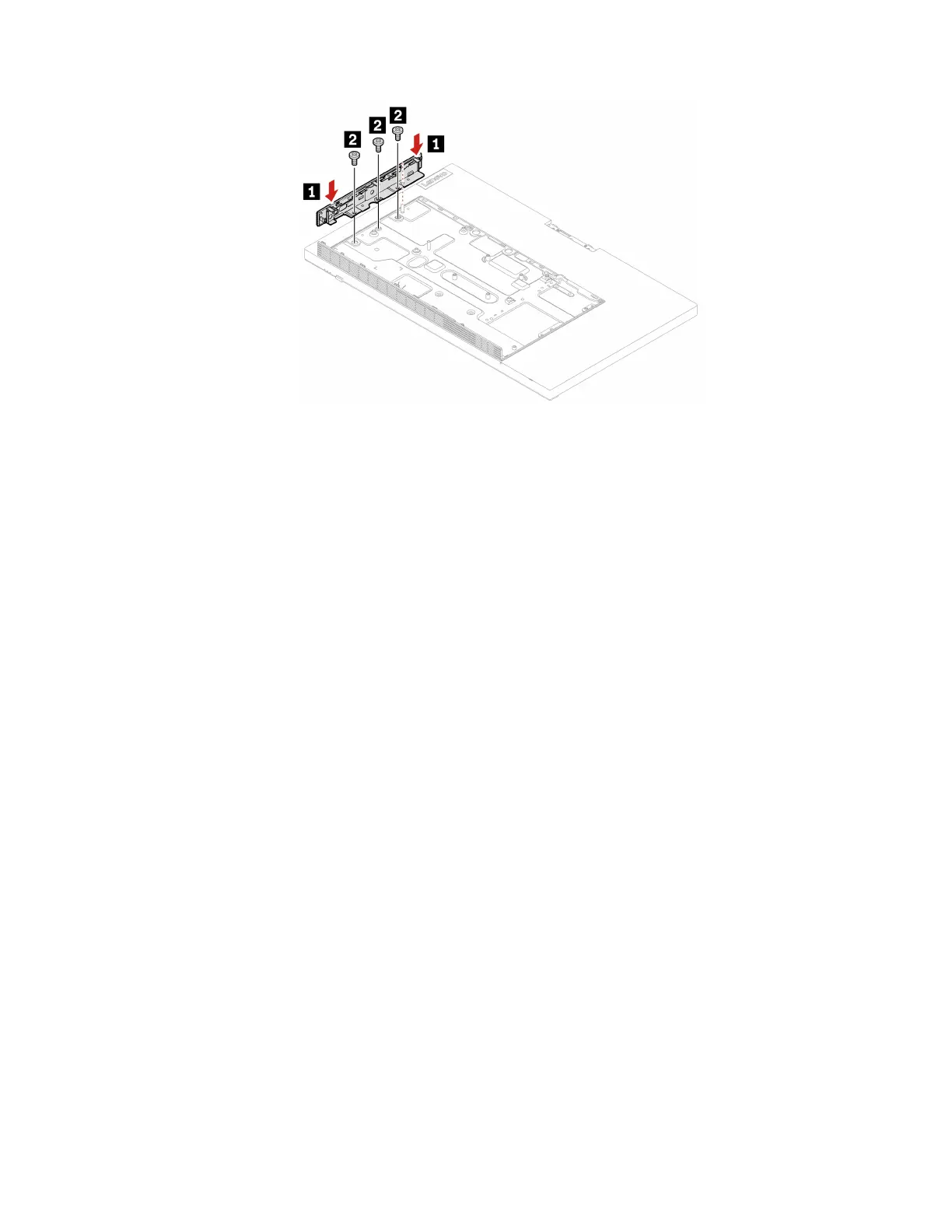
Figure 140. Installing the right I/O bracket
21. Reinstall the removed parts.
22. Place the computer in an upright position.
23. If a locking device is available, use it to lock the computer.
24. Reconnect the external cables and power cords to the corresponding connectors on the computer.
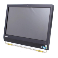
Integrated camera and microphone module
Prerequisite
Before you start, read Chapter 1 “Important safety information” on page 1 and print the following
instructions.
Replacement procedure
1. Remove the computer stand. See “Computer stand” on page 61.
2. Remove the rear cover. See “Rear cover” on page 65.
3. Remove the optical drive. See “Optical drive” on page 66.
4. Remove the optical drive holder. See “Optical drive holder” on page 69.
5. Remove the system board shield. See “System board shield” on page 71.
6. Remove the VESA mount bracket cover. See “VESA mount bracket cover” on page 74.
7. Remove the VESA mount bracket. See “VESA mount bracket” on page 76.
8. Disconnect the integrated camera and microphone module cable from the system board.
9. Depending on your computer model, refer to one of the following to replace the integrated camera and
microphone module.
CAUTION:
Do not pull out the integrated camera and microphone module cable with force; otherwise, the
cable may be damaged.
• M70a
Chapter 6. Hardware removal and installation 127
 Loading...