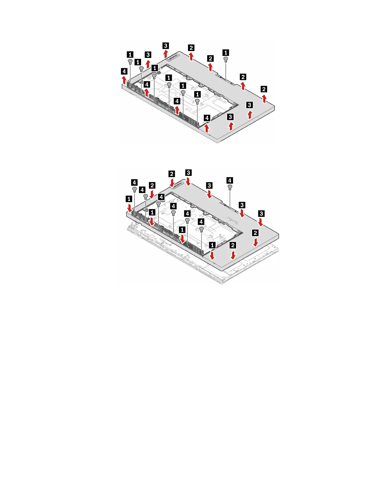
Figure 151. Removing the main frame
Figure 152. Installing the main frame
26. Reinstall the removed parts.
27. Place the computer in an upright position.
28. If a locking device is available, use it to lock the computer.
29. Reconnect the external cables and power cords to the corresponding connectors on the computer.
Front decoration cover
Attention: Do not open your computer or attempt any repairs before reading the Important Product
Information Guide.
1. Remove the computer stand. See “Computer stand” on page 61.
2. Remove the rear cover. See “Rear cover” on page 65.
3. Remove the optical drive. See “Optical drive” on page 66.
4. Remove the optical drive holder. See “Optical drive holder” on page 69.
5. Remove the system board shield. See “System board shield” on page 71.
6. Remove the VESA mount bracket cover. See “VESA mount bracket cover” on page 74.
Chapter 6. Hardware removal and installation 133
 Loading...