Configuration
8-10
BA9300SU EN 2.1
8.3.4 Entries into the processing table
The 93XXcontroller providesacertaintime forcalculating theprocessing timeof FBs. Since thetype
and number of FBs to be used depends on the application and can vary strongly, not all available
FBs arepermanently calculated. Aprocessing table is thereforeprovided under code C0465, where
only the FBs used are listed. This means that the drive system is perfectly matched to the task. If
further function blocks are integrated into an existing configuration, these must be listed in the
processing table.
Several aspects must be observed:
The number of FBs to be processed is limited
Amaximum of 50 FBs can be integrated into aconfiguration. Every FB requires a certainprocessing
time. Code C0466 displays the residual time for the processing of FBs. If this time has elapsed no
further FBs can be integrated.
Entry sequence into the FBs
Normally, the entry sequence under C0465 is arbitrary, but it may be important for applications with
high response. In general, the most favourable sequence is adapted to the signal flow.
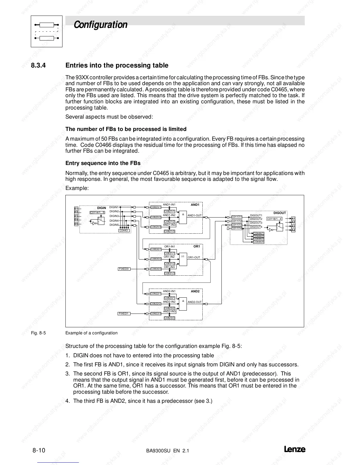
Example:
AND1
&
AND2
&
OR1
≥1
E1
E2
E3
E4
E5
DIGIN
A1
A2
A3
A4
DIGOUT
Fig. 8-5 Example of a configuration
Structure of the processing table for the configuration example Fig. 8-5:
1. DIGIN does not have to entered into the processing table
2. The first FB is AND1, since it receives its input signals from DIGIN and only has successors.
3. The second FB is OR1, since its signal source is the output of AND1 (predecessor). This
means that the output signal in AND1 must be generated first, before it can be processed in
OR1. At the same time, OR1 has a successor. This means that OR1 must be entered in the
processing table before the successor.
4. The third FB is AND2, since it has a predecessor (see 3.)
 Loading...

