Mechanical installation
Mounting of motors on gearboxes with mounting flange (drive-end version N)
Mounting the clamping ring hub
4
28
BA33.0001 EN 2.0
4.3.5 Mounting the clamping ring hub
1
2
3
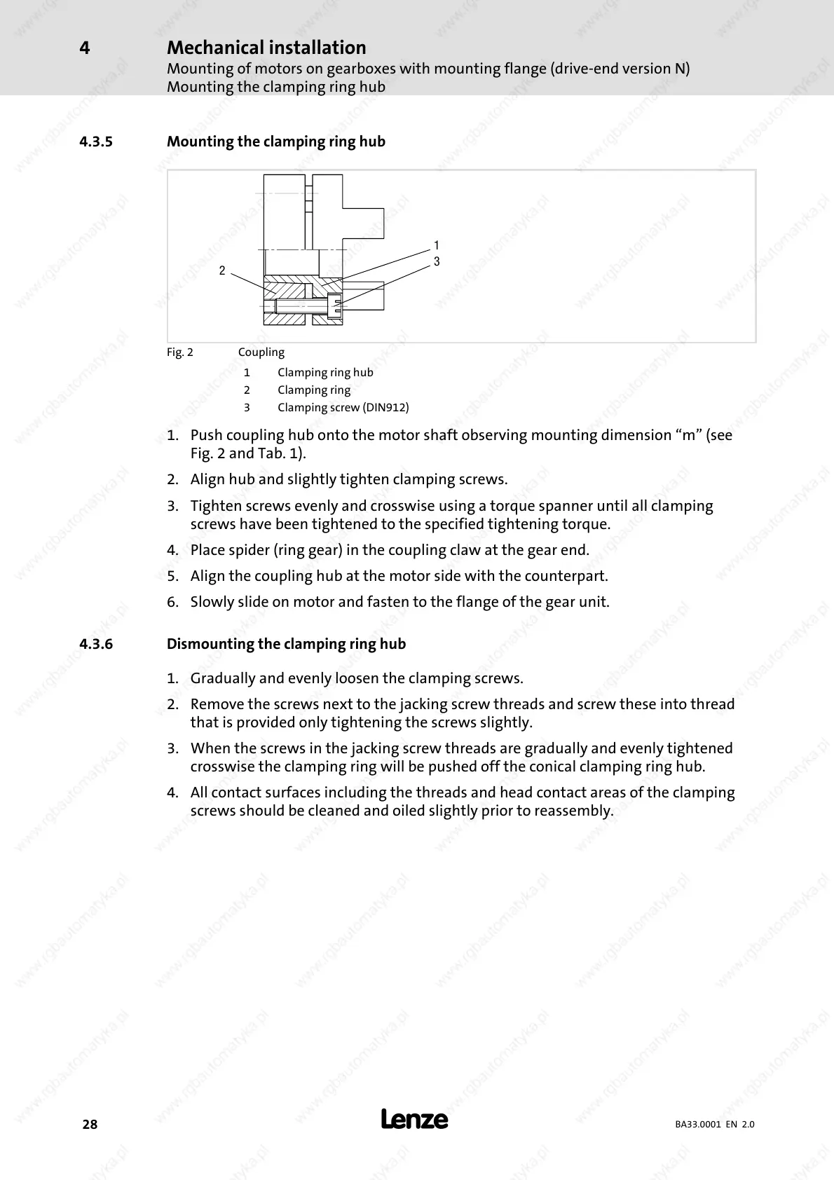
Fig. 2 Coupling
1 Clamping ring hub
2 Clamping ring
3 Clamping screw (DIN912)
1. Push coupling hub onto the motor shaft observing mounting dimension “m” (see
Fig. 2 and Tab. 1).
2. Align hub and slightly tighten clamping screws.
3. Tighten screws evenly and crosswise using a torque spanner until all clamping
screws have been tightened to the specified tightening torque.
4. Place spider (ring gear) in the coupling claw at the gear end.
5. Align the coupling hub at the motor side with the counterpart.
6. Slowly slide on m otor and fasten to the flange of the gear unit.
4.3.6 Dismounting the clamping ring hub
1. Gradually and evenly loosen the clamping screws.
2. Remove the screws next to the jacking screw threads and screw these into thread
that is provided only tightening the screws slightly.
3. When the screws in the jacking screw threads are gradually and evenly tightened
crosswise the clamping ring will be pushed off the conical clamping ring hub.
4. All contact surfaces including the threads and head contact areas of the clamping
screws should be cleaned and oiled slightly prior to reassembly.
 Loading...