9
Installation
Observe the following when using E.l.c.b:
• Installation of E.l.c.b only between supplying mains and controller.
• The E.l.c.b can be activated by:
- capacitive leakage currents between the cable screens during operation (especially with long,
screened motor cables)
- connecting several controllers to the mains at the same time
- RFI filters
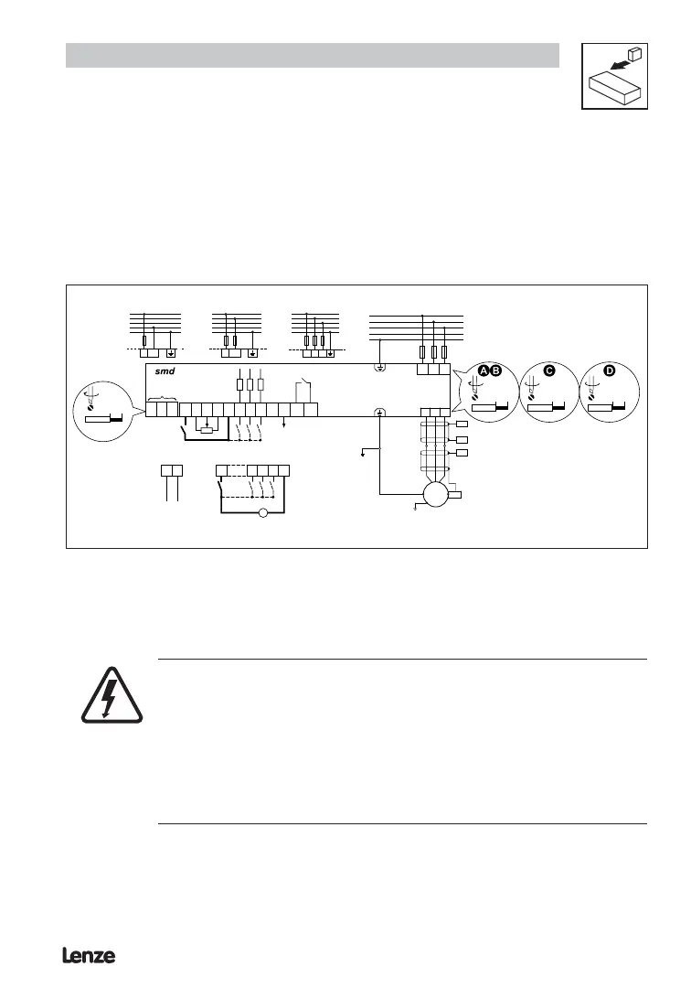
3.2.3 Connection diagram
U V W
L1 L2 L3
PE
N
L3
L2
L1
3/PE 320V - 0 % … 528V + 0 %
48 Hz … 62 Hz
0.5 Nm/ 4.5 lb-in
6 mm /0.24 in
0.2 Nm/ 2 lb-in
6 mm /0.24 in
< 1mm
2
/AWG 26…16
_
L1
L2
PE
N
L3
L2
L1
3/PE 180V - 0% … 264V + 0 %
48 Hz … 62 Hz
L3
1.2 Nm/ 10 lb-in
9 mm /0.35 in
2.0 Nm/ 18 lb-in
13 mm /0.5 in
L2/N
PE
N
L3
L2
L1
2/PE 180V - 0% … 264V + 0 %
48 Hz … 62 Hz
L1
PE
N
L3
L2
L1
1/N/PE 180V - 0% … 264V + 0 %
48 Hz … 62 Hz
L2/N
L1
PES
PE
PES
PES
M
3~
PES
PE
2098728
E1
E2
E3 7
62
K14
K12
+12V
+10V
AI N
COM
COM
AOUT
7
28
E1 E2
7
8
E3
-
+
+12 VDC - 0 %
…
+30 VDC + 0 %
0 … 20 mA
4 … 20 mA
GND
L H
CAN
C0002
Danger!
• Hazard of electrical shock! Circuit potentials are up to 240 VAC above earth ground.
Capacitors retain charge after power is removed. Disconnect power and wait until
the voltage between B+ and B- is 0 VDC before servicing the drive.
• Do not connect mains power to the output terminals (U,V,W)! Severe damage to
the drive will result.
• Do not cycle mains power more than once every three minutes. Damage to the
drive will result.
 Loading...