30
Commissioning
4.5 Quick CAN set-up
1. Power up the controller and set h50 (CAN address) and h51 (CAN baud rate) to
appropriate values.
2. Power down the controller and connect the communication cable. For reliable
communication make sure terminal CAN_GND is connected to CAN network GND/
common. If only two wires are used (CAN_H and CAN_L) in the network, connect
CAN_GND to chassis/earth ground.
3. Power up the controller.
4. Use Global Drive Control Software to configure the required operation of the controller.
Example: Controller #2 needs to follow the operation of controller #1 (start/stop, speed, etc).
Controller #1 can be controlled by CANopen or traditional control elements (relays, etc).
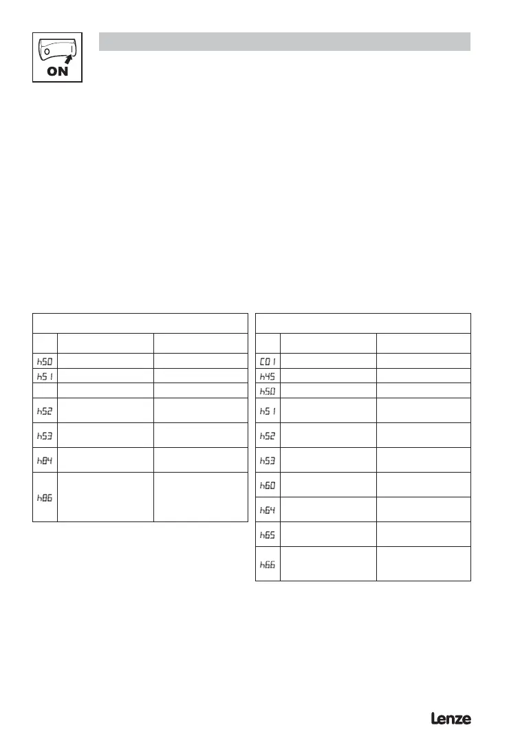
Controller #1 conguration Controller #2 conguration
No. Name Setting No. Name Setting
h50
CAN address (Node ID) 1
C01
Setpoint source 3 CANopen control
h51
CAN baud rate 5 500 kbps
h45
Error behavior 1 No state change
h50
CAN address (Node ID) 2
h52
System bus participant
1 Slave with
autostart enabled
h51
CAN baud rate 5 500 kbps
h53
Parameter channel 2
(SDO#2)
0 Enable with default
COB ID
h52
System bus participant
1 Slave with
autostart enabled
h84
TPDO#1 event timer 10 ms
h53
Parameter channel 2
(SDO#2)
1 Enable with prog.
COB ID
h86
TPDO#1 mapping
3 Controller status
in C0135 format +
frequency setpoint
unsigned
h60
RPDO#1 COB ID
385
(h80 from controller #1)
h64
RPDO#1 event
monitoring timer
50 ms
h65
RPDO#1 time out
reaction
1 Inhibit
h66
RPDO#1 mapping
1 C0135 control word
+ C46 frequency
setpoint unsigned
After setting the parameters, perform Node reset using parameter h58 or cycle the power.
After these controllers are configured as above, controller #2 will follow the operation of
controller #1 including: Inhibit state, Quick Stop, DC brake, JOG speed selections, direction,
and speed. For additional safety, controller #2 will transition to inhibit state if valid PDO is
not received from controller #1 within 50ms.
 Loading...