29
Commissioning
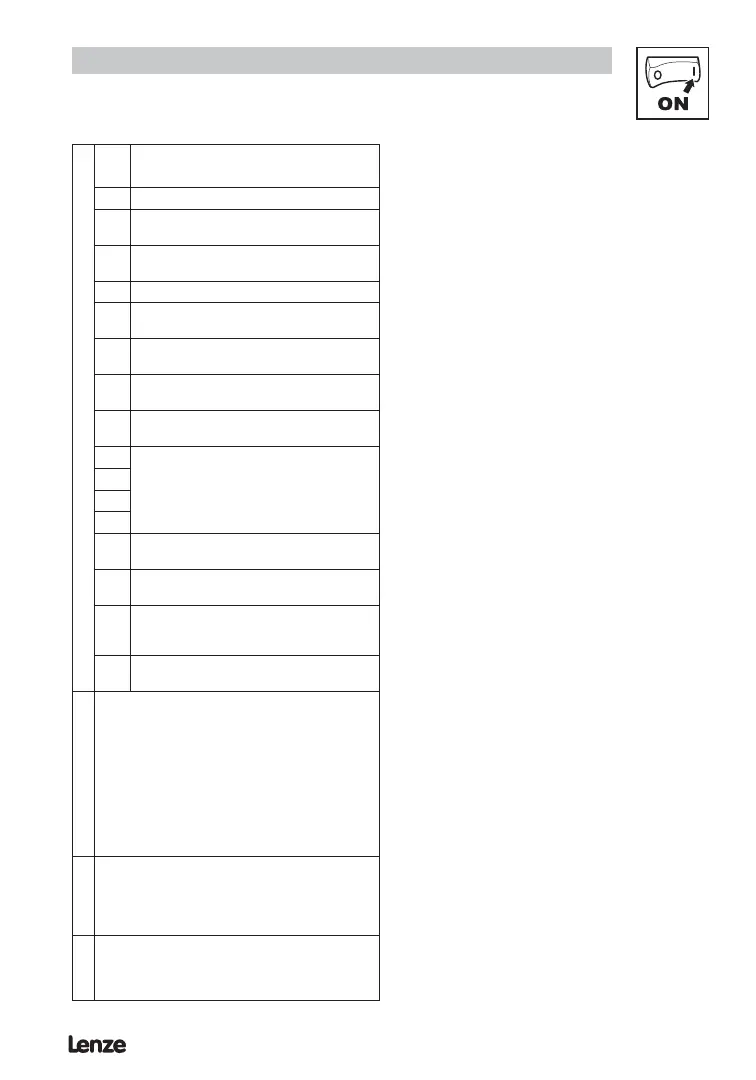
WORD0 - C0150 Status word
Bit h86 / h96 setting = 6
0 reserved
1
0 = Pulses to power stage enabled
1 = Pulses to power stage Inhibited
2
0 = Current limit not reached
1 = Current limit reached
3 reserved
4
0 = Actual frequency < > setpoint
1 = Actual frequency = setpoint
5
0 = Not above threshold
1 = Above threshold (C17)
6
0 = Actual frequency < > 0 Hz
1 = Actual frequency = 0 Hz
7
0 = No controller inhibit
1 = Controller inhibit
8
Controller status
0 = no fault
8 = fault present
9
10
11
12
0 = No overtemperature warning
1 = Overtemperature warning
13
0 = No DC bus overvoltage
1 = DC bus overvoltage
14
Direction of rotation
0 = CW (forward)
1 = CCW (reverse)
15
0 = Not ready
1 = Ready (no faults)
WORD1
• Signed output frequency read from C50
signed scaled +/- 16384 = C11 (max frequency)
• Scaling = C50*16384/C11
• Example 1: WORD1 = 0x2C29, C11 = 50.0Hz
Direction = Sign(0x2C29) = CW
Frequency = ABS(0x2C29) * C11 /16384
= 11305*50/16384 = 34.5 Hz CW
• Example 2: WORD1 = 0xC70A, C11 = 50.0Hz
Direction = Sign(0xC70A) = CCW
Frequency = ABS(0xC70A) * C11 /16384
= 14582*50/16384 = 44.5 Hz CCW
WORD2
Digital inputs status (TB28,E1,E2,E3)
• Bit 0 - TB28 state (1 - asserted)
• Bit 1 - E1 state (1 - asserted)
• Bit 2 - E2 state (1 - asserted)
• Bit 3 - E3 state (1 - asserted)
WORD3
Analog input value 0-1000 -- corresponds to 0-10V
ex. 400 -> 4.00V
 Loading...