10
Installation
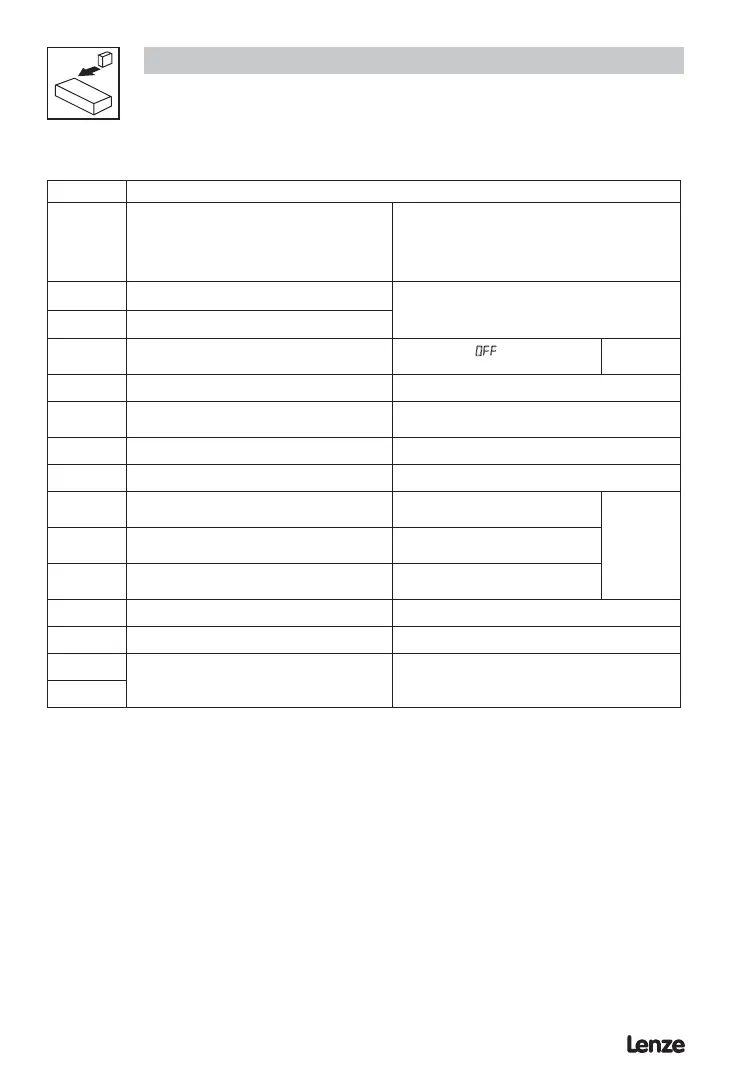
Terminal
Data for control connections (printed in bold = Lenze setting)
CAN_GND
CAN earth ground
For reliable communication make sure terminal
CAN_GND is connected to CAN network
GND/common. If only two wires are used (CAN_H
and CAN_L) in the network, connect CAN_GND to
chassis/earth ground.
CAN_L
CAN low If controller is located at either end of the network,
a terminating resistor (120Ω typical) should be
connected across CAN_L and CAN_H
CAN_H
CAN high
28
Digital input Start/Stop
LOW = Stop (OFF)
HIGH = Run Enable
R
i
= 3.3 kΩ
7
Reference potential
8
Analog input
0 … 10 V (changeable under C34)
input resistance: >50 kΩ
(with current signal: 250Ω)
9
Internal DC supply for setpoint potentiometer +10 V, max. 10 mA
20
Internal DC supply for digital inputs +12 V, max. 20 mA
E1
Digital input configurable with CE1
Activate xed setpoint 1 (JOG1)
HIGH = JOG1 active
R
i
= 3.3 kΩ
E2
Digital input configurable with CE2
Direction of rotation
LOW = CW rotation
HIGH = CCW rotation
E3
Digital input/output configurable with CE3
Activate DC injection brake (DCB)
HIGH = DCB active
7
Reference potential
62
Analog output configurable with c08 & c11
K14
Relay output (normally-open contact)
Configurable with C08
Fault (TRIP)
AC 250 V / 3 A
DC 24 V / 2 A … 240 V / 0.22 A
K12
LOW = 0 … +3 V, HIGH = +12 … +30 V
Protection against contact
• All terminals have basic isolation (single insulating distance)
• Protection against contact can only be ensured by additional measures (i.e. double insulation)
3.2.4 Control terminals
 Loading...