- 50 -
Copyright ©2008 LG Electronics. Inc. All right reserved.
Only for training and service purposes
LGE Internal Use Only
Replacement Procedure for INV PCB
Caution for Assembling Outdoor Panels after Test Run
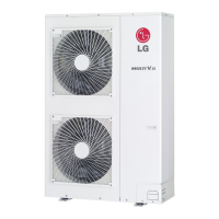
If the connection between wires is incorrect, performance of the unit would be decreased.
CAUTION
After replace the INV PCB assembly, make sure that connection of fan motor wires is correct.
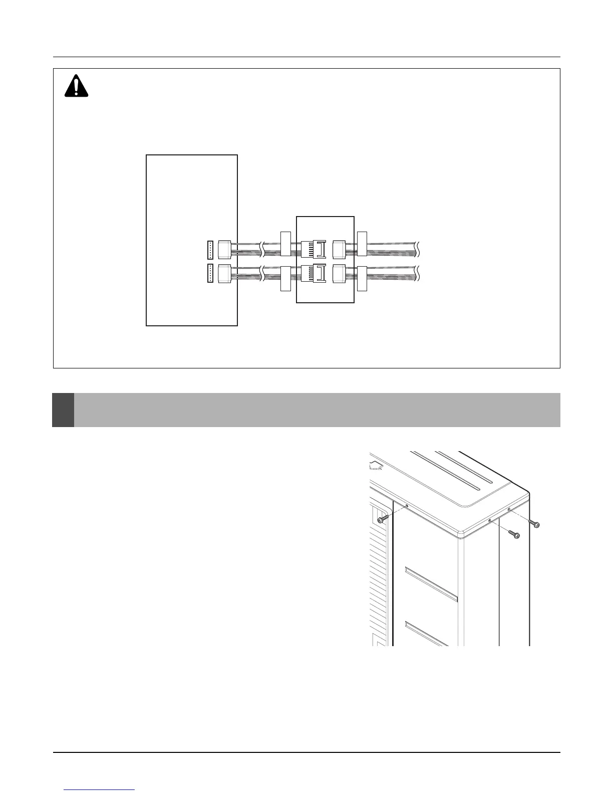
When assemble the outdoor panels after replacement, make sure
that screws of top panel are assembled as shown figure below.
If screws are not assembled, it allows rain come into control box
causing defect of unit.
Main PCB Case
to Fan moter
Fan motor wire
terminal (UP)
Fan motor wire
terminal (DOWN)
to Fan moter
INV. PCB
UP
DOWN
UP
DOWN
 Loading...