- 56 -
Copyright ©2008 LG Electronics. Inc. All right reserved.
Only for training and service purposes
LGE Internal Use Only
Checking Method for Key Components
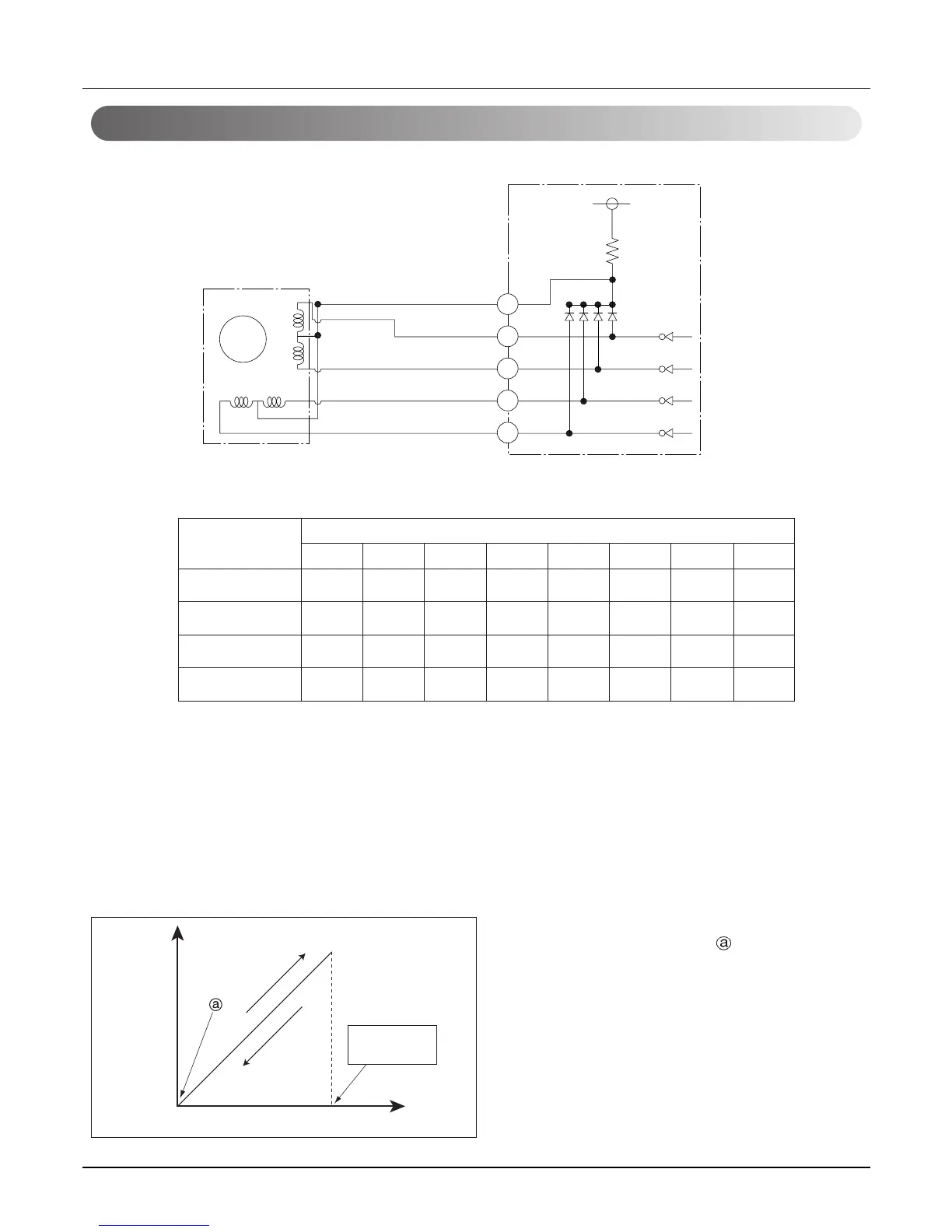
EEV
M
13
2
6
4
ø5 Red
White
Yellow
Orange
Blue
5
4
3
2
ø4
DC 12V Driving
circuit
ø3
ø2
ø1
1
ø4
ø3
ø2
ø1
• Pulse signal output value and valve operation
• Output pulse sequence
- In valve close state: 1 → 2 → 3 → 4 → 5 → 6 → 7 → 8 → 1
- In valve open state: 8 → 7 → 6 → 5 → 4 → 3 → 2 → 1 → 8
1. If EEV open angle does not change, all of output phase will be OFF
2. If output phase is different or continuously in the ON state, motor will not operate smoothly and start vibrat-
ing.
• EEV valve operation
ø1 ON OFF OFF OFF OFF OFF ON ON
ø2 ON ON ON OFF OFF OFF OFF OFF
ø3 OFF OFF ON ON ON OFF OFF OFF
ø4 OFF OFF OFF OFF ON ON ON OFF
Output(ø) No.
Output state
12345678
Valve
open
Angle
close
pulse
open
Full open
1350 pulses
- At power ON, open angle signal of 1400 pulses out-
put and valve position is set to
If valve operates smoothly, no noise and vibration
occurs and if valve is closed. noise occurs.
- Noise from EEV can be confirmed by touching the
EEV surface with a screw driver and listening the
EEV noise.
- If liquid refrigerant is in EEV, the noise is lower.
2.3 Electronic Expansion Valve
 Loading...