- 46 -
Copyright © 2020 LG Electronics Inc.
All rights reserved. Only training and service purposes.
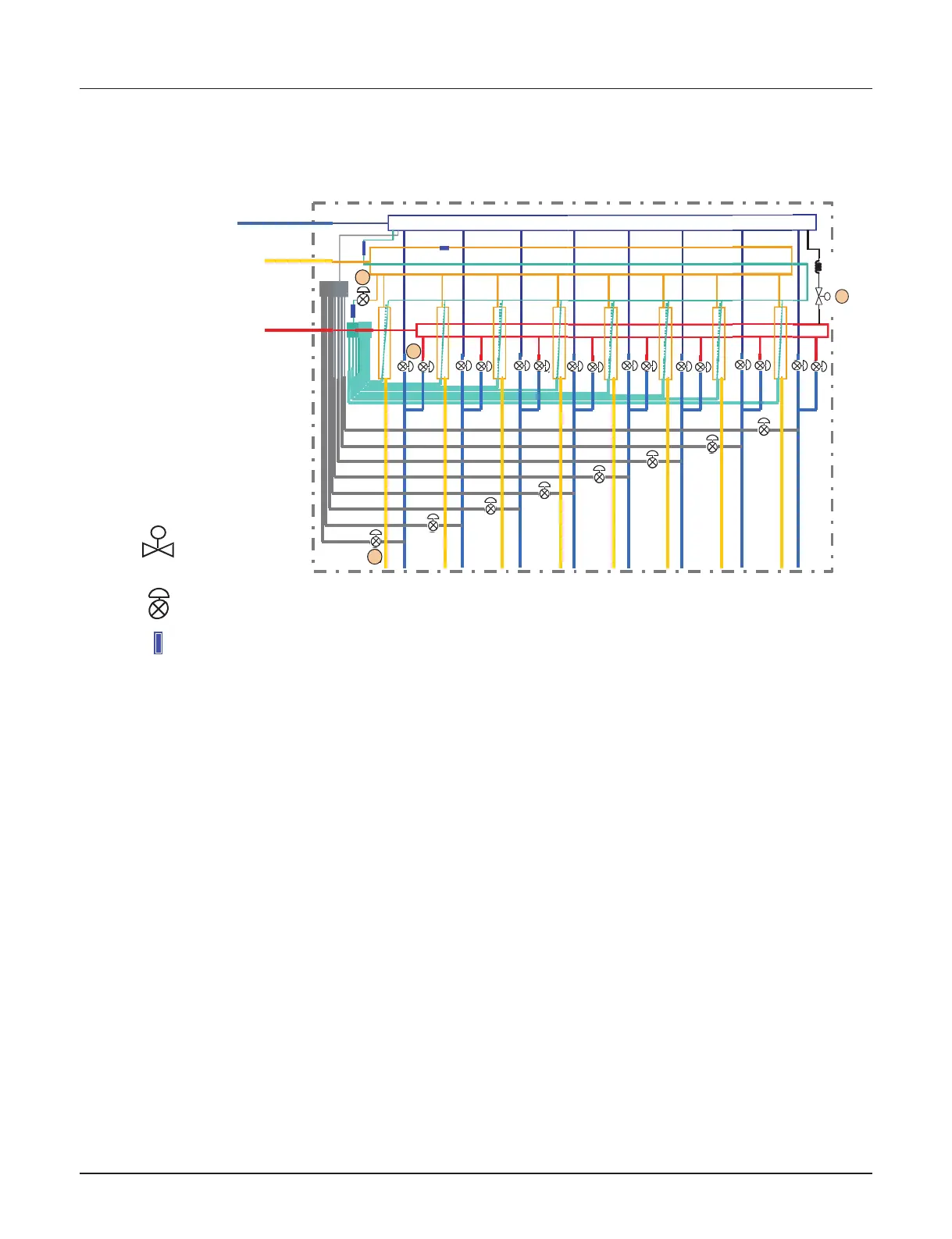
Piping Diagrams
Ⓐ : To be switched operation between cooling and heating by two valves
Ⓑ : To be used decreasing noise according to sub-cooling of inlet and outlet of indoor unit
(Simultaneous operation)
Ⓒ : To prevent liquid charging between high pressure gas valve and HR unit at cooling mode
Ⓓ : To be controlled the pressure between high and low pressure pipe during operation switching
 Loading...