MX-FR Series Modular Matrix Frames – User's Manual 103
Setting the Parameters
The signal type is set to DVI, the other parameters have not been changed. Use the 'x' character
to keep the actual value of a parameter. The response contains the new settings in the <OUT_SET> block;
see the details in the Legend.
Legend
<gen_info> block
Format: G<a><b><c><d><e>
G11101
Sink device is attached to the port and HDMI signal is routed to the port. HDCP is disabled and hotplug is
detected.
<video> block
INFO: This block is present only if a valid video signal is present on the selected port.
character of this block is V.
Format: V<Resolution>,<Hsync>,<Color_space>
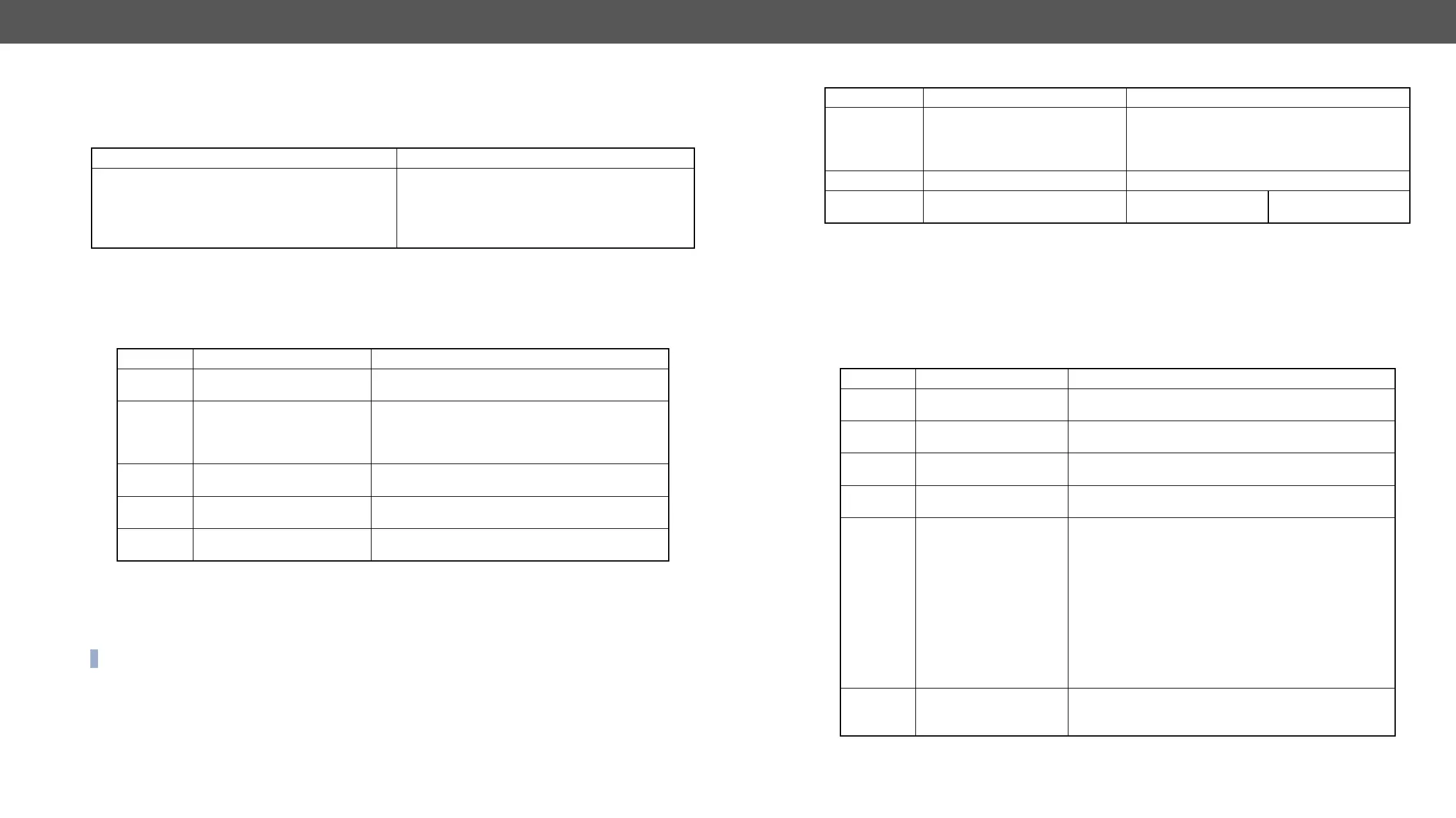
Format
Command
<a>;<b>;<c>;<d>;<e>;}
→
{:hdmi#1@so=D;x;x;x;x;}
Response
<VIDEO>;<ADV_INFO>;<OUT_SET>;
<SINK>;)CrLf
←
(HDMI#1@SO=G10101;V720x576p51,313,00;
I001100;ODAAAA;M110111077;)CrLf
Parameter Description Parameter Values
<a> Sink is connected
0 = no attached sink device
1 = sink device is present
<b> Signal type
0 = DVI signal is transmitted
1 = HDMI signal is transmitted (no deep color)
2 = HDMI signal is transmitted (deep color, 30 bit)
3 = HDMI signal is transmitted (deep color, 36 bit)
<c> Signal validity
0 = No valid signal is routed to the port
1 = Valid video signal is present
<d> HDCP state
0 = HDCP encryption is disabled
1 = HDCP encryption is active
<e> Hotplug detection
0 = Hotplug detect signal is low
1 = Hotplug detect signal is high
V1920x1080p60,675,00
1080p60 signal is detected with progressive scan at 60 Hz refresh rate; vertical sync value is 675 kHz and
the signal is in RGB 4:4:4 color space.
<adv_info> block
For advanced users this block provides information which could be useful during debugging process. The
Format: I<a><b><c><d><e><f>
I111190.
Positive HSYNC and VSYNC, stable pixel clock, 4:3 aspect ratio and no pixel repetition.
Parameter Description Parameter Values
<Resolution>
<Height> = active video height (pixels)
<Scan> = p: progressive, i: interlaced scan mode
<Vsync> value (Hz)
Horizontal sync <Hsync> value (kHz)
<Color_space> Color space information
00 = RGB444
10 = YUV422
20 = YUV444
Parameter Description Parameter Values
<a> VSYNC polarity
0 = VSYNC polarity is negative (leading edge falls)
1 = VSYNC polarity is positive (leading edge rises)
<b> HSYNC polarity
0 = HSYNC polarity is negative (leading edge falls)
1 = HSYNC polarity is positive (leading edge rises)
<c>
TMDS clock line signal
presence
0 = There is no change on the TMDS clock line
1 = Signal is present on the TMDS clock line
<d> TMDS clock line stability
0 = The clock signal is unstable on the TMDS clock line
1 = The clock signal is stable on the TMDS clock line
<e>
Active Format Aspect
Ratio based on AVI
InfoFrame
0 = Field is not present (e.g. DVI signal)
2 = 16:9 (top)
3 = 14:9 (top)
4 = greater than 16:9 (center)
5 = Same as picture aspect ratio
9 = 4:3 (center)
A = 16:9 (center)
B = 14:9 (center)
D = 4:3 (with shoot and protect 14:9 center)
E = 16:9 (with shoot and protect 14:9 center)
F = 16:9 (with shoot and protect 4:3 center)
<f>
Pixel repetition factor
based on AVI InfoFrame
0 = No repetition (i.e. pixel sent once)
1 = Pixel sent 2 times (i.e. repeated once)
3 = Pixel sent 4 times