MX-FR Series Modular Matrix Frames – User's Manual 117
Binary
(B#In=[received text as binary data, e.g. 736F6D657468696E67]) or
(B#On=[received text as binary data, eg. 736F6D657468696E67])
where n is the port number, I refers input, O stands for the output ports.
The received text is translated to binary form. The maximum length of the received text is 54 byte, so the
length of the hex data can be up to 108 characters.
Far endpoint, connected to input port 1 is sending data, the router sends:
(B#I1=736F6D657468696E67)
Description: The properties of the serial pass-through can be queried on the input and the output side.
Serial pass-through sending and receiving is enabled on the 9th output port with 9600 baud.
Legend
Setting the Serial Parameters
Description:
Serial pass-through sending and receiving is enabled on the 9th output port with 9600 baud.
Legend: See the previous section.
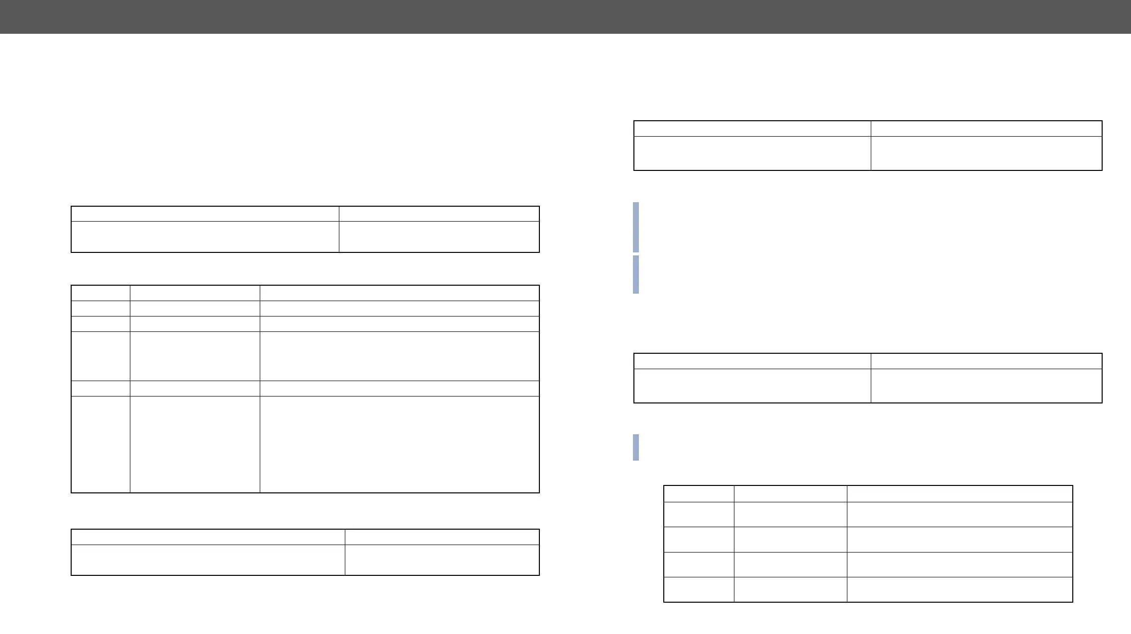
Format
Command
→
{:serial#9@so=?}
Response
←
(SERIAL#9@SO=1;9600;8N1)CrLf
Parameter Description Parameter Values
<in
2
>/<out
2
> Input or output port number Output number in 1 or 2 digit ASCII format (01, 3, 04 etc.)
<I/O> Input or output port type I = input, O = output
<a> Receiving mode
0: Disabled (incoming data is ignored but sending is allowed)
1: The incoming data is sent to the controllers in ASCII mode.
(default)
2: The incoming data is sent to the controllers in HEX mode.
<b> Current baud rate 9600, 14400, 19200, 38400, 57600 (default), 115200
<c>
Port setting
(in standard format e.g.
8N1)
1st character: number of data bits: 5, 6, 7 or 8 (default)
2nd character: parity bit. Possible values are:
N: No parity (default)
O: Odd parity
E: Even parity
M: Fixed high (Mark)
S: Fixed low (Space)
3rd character: number of stop bits: 1 (default) or 2
Format
Command
→
{:serial#9@so=1;9600;8n1}
Response
←
(SERIAL#9@SO=1;9600;8N1)CrLf
Router Initiated Commands
EDID Status Changed
Description: This is sent after any command which changed the EDID table (EDID copy, EDID switch), or if a
new EDID source e.g. a new display device is connected to the router.
router shows that an EDID has changed.
INFO:
by the router if a display device having the same EDID is connected to that output. (The same display
device is connected again, or another display device (same brand) from the same manufacturer).
INFO: To keep your application in sync with the router it is recommended to issue a watch validity ( {wvd},
the table, as the change of these EDIDs triggered the (E_S_C) message.
Description: This message is sent when any value changes in the response for the {PS} command. The
or disconnected.
An input port (which had signal present before) detects no signal. The router sends a message
to indicate port status change.
INFO: The (PSC) message can be omitted by a third party controller, or it can be used to trigger a {PS}
command. In the latter case, the controller can be up to date with the port status without continuous queries.
Error Responses
Format
Command various a new monitor is connected to the output
Response (E_S_C)CrLf
←
(E_S_C)CrLf
Format
Command none an input port looses signal
Response (PSC)CrLf
←
(PSC)CrLf
Response Error type Description
(ERR01)CrLf Invalid input number
Given input number exceeds the maximum
number of inputs or equals zero.
(ERR02)CrLf Invalid output number
Given output number exceeds the installed
number of outputs or equals zero.
(ERR03)CrLf Invalid value
Given value exceeds the maximum allowed value
can be sent.
(ERR04)CrLf Invalid preset number
Given preset number exceeds the maximum
allowed preset number.