4. Operation MX-FR Series Modular Matrix Frames – User's Manual 52
Avoid Causing an Ethernet Loop
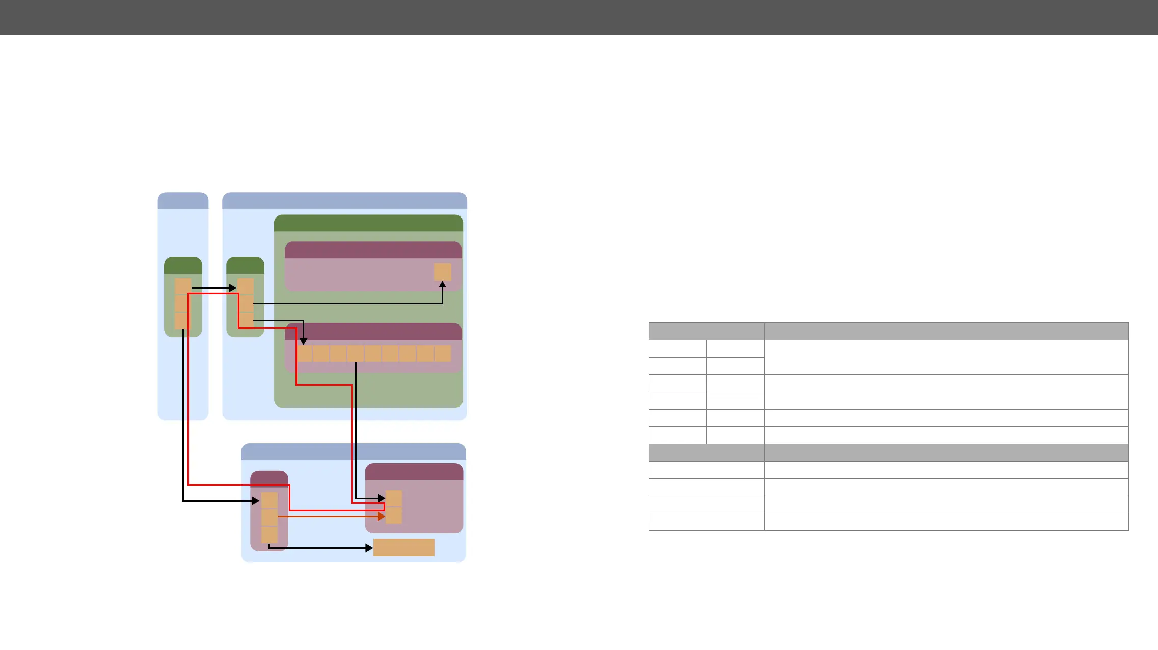
A TPS board (actually the Ethernet switch of the board) can be uplinked to the same LAN only once to avoid
an Ethernet loop. In this case, if the other network devices are not able to handle Ethernet loops, the LAN
network may break down.
Example
in the ROOM 3 is connected to the LAN via TPS link. If the installer does not know the transmitter has already
connected to the LAN via TPS and links the transmitter to the switch – shown by the brown arrow in the
picture – it results in an Ethernet loop – demonstrated by the red lines on the picture below.
Ethernet Loop
MX-CPU2
ROOM 2
1 2 3 4 5 6 7 8
Switch
ETH
ETH
1
2
3
MX-TPS-IB-A
MX-FR frame
ROOM 1
Router
1
2
3
ROOM 3
Switch
ETH
1
3
HDMI-TPS-TX95
TPS
Ethernet device
2
LCD Control Panel Operation
Basic Concept
There are three operating modes of the LCD menu.
Normal Mode
Most settings can be done in this mode. It is active when none of the EDID or the SIGNAL PRESENT button
shine.
EDID Mode
Use this mode to set up the emulated EDID on the inputs, learn EDID form the outputs or to view the EDID
memory. Enter or exit this mode by pressing the EDID button. The illuminated EDID button shows that this
mode is active.
Signal Present Mode
This mode is for checking the presence of incoming signals and display devices. Enter or exit this mode by
pressing the SIGNAL PRESENT button. The illuminated SIGNAL PRESENT button shows that this mode is active.
Navigation
The front panel LCD has 4 lines and 20 characters in each line. The navigation buttons and the applied
symbols are listed as follows:
Button Function
up
scroll between menu items
down
left
right
enter step in a submenu or execute changes
escape step back to the previous submenu
Symbol Function
~
indicates the currently selected menu item
>>
shows the current submenu
< and >
changeable values are in angle brackets
[*]
indicates an active function

 Loading...