4
lci1.com 574 - 537- 890 0 Rev: 11.16.18
Solera
®
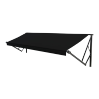
Classic Awning
Installation and Owner’s Manual
(For Aftermarket Applications)
CCD-0001254
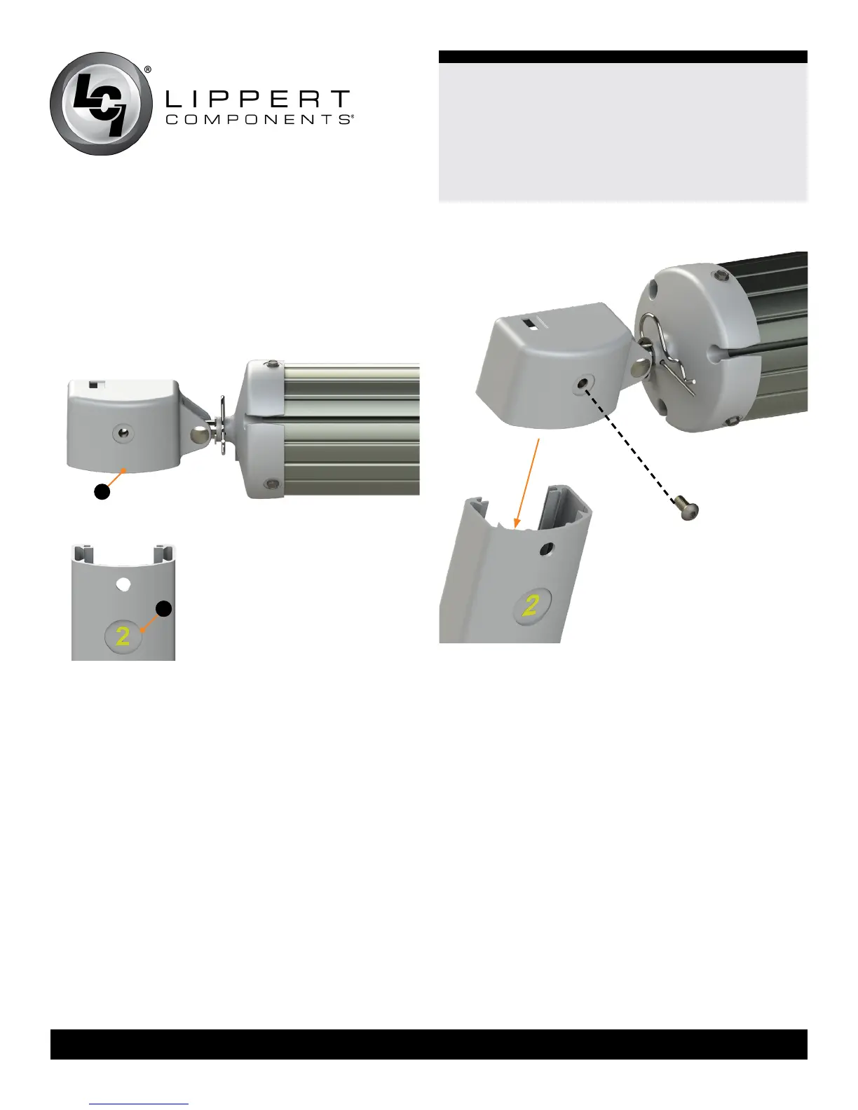
Assembling the Awning
NOTE: The head assemblies (Fig.2A) and support arm
assemblies (Fig.2B) are numbered to ensure proper
assembly. Match the proper support arm assembly to the
correct head assembly.
Fig.3
Fig.2
A
B
NOTE: Do not set the awning on any surface that may
damage the assembly or fabric.
1. On a at surface, carefully lay out the support arm
assemblies and roll tube assembly.
NOTE: The cam lock MUST be on the right side of the roll
tube when facing the unit.
2. Slide the left support arm assembly into the idler head
assembly of the roll tube. Align the holes and secure using
one (1) ¼”-20 x ½” Phillips head drive screw (Fig.3).
3. Repeat step 2 for the right support arm assembly.
4. Measure and conrm the width of the awning. The
distance is measured from bolthead to bolthead (Fig.1).
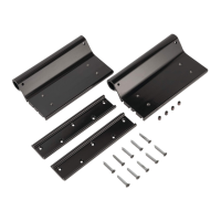
Installing the Bottom Mounting Brackets
1. On the awning rail, mark the position of the support arm
assemblies using the bolthead-to-bolthead measurement.
Ensure that the support arm assemblies will not interfere with
any lights, vents or the operation of any windows or doors.
2. Using a non-permanent method of marking, mark a
perpendicular line from the mark on the awning rail down
to the oor line. This is the centerline of the support arm
assembly (Fig.1). Do this for both support arm assemblies.
3. Position the bottom bracket with the fastening points at the
oor line (Fig.4).
A. Center the bracket on the centerline mark of the
support arm assembly (Fig.4).
B. Mark the hole locations, then using a 3/16” drill bit, pre-
drill both holes.
C. Apply a liberal amount of sealant over the holes.
D. Attach the bracket using the provided ¼” x 2 ½” lag
screws (Fig.4).
 Loading...