REG. CODE
1-5302-351
MODEL N°
50563
DATE OF ISSUE
04.90
REVISION 04
DATE
15.11.99
ENDORSED
COMPILER TECO/ATI
52
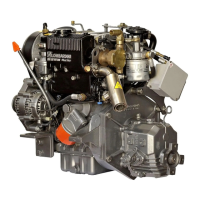
CONNECTING BEARING / ROD CAP INSTALLATION
Install the connecting rod bearing inserts into the connecting rod and
connecting rod cap. Make sure that the back of the bearing insert and
the connecting rod and connecting rod cap bore is free of dirt, rust,
oil etc. Insert the bearing inserts so that the tab on the bearing aligns
with the slot in the connecting rod or connecting rod cap. Push the
bearing completely into the connecting rod and connecting rod cap.
Liberally oil the bearings with clean engine oil. Install the connecting
rod cap onto the connecting rod making sure that the respective
tang/slot locks on the connecting rod cap aligns with the tang/ slot
lock on the connecting rod.
Torque the connecting rod bolts to 40 Nm in 5 Nm steps.
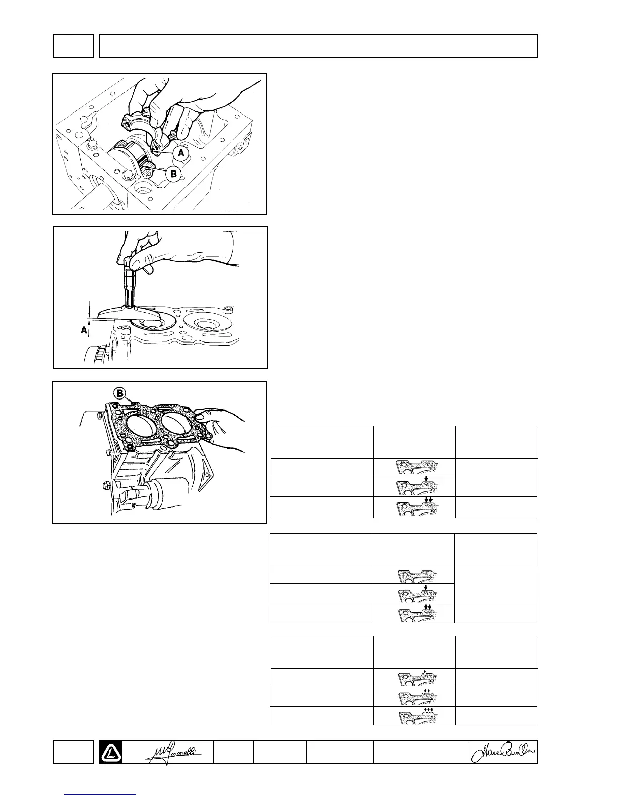
PISTON PROTRUSION
Rotate each cylinder to exact TDC. TDC may be determined by the
use of a dial indicator mounted to the cylinder deck and indicating
piston height as a function of crankshaft rotation.
After TDC is established, measure the protrusion of the piston (A)
from the cylinder deck plane using a calibrated depth micrometer.
The height should be measured on a line corresponding to the wrist
pin axis as shown. Record the protrusion. Repeat the TDC
establishment and piston protrusion procedure for each cylinder,
recording the value for each cylinder. The HIGHEST protrusion
measured will be used to establish the proper head gasket selection
as presented below.
HEAD GASKET SELECTION/ INSTALLATION
Three(3) separate head gasket thickness’ are available for FOCS
engines depending on the measured piston protrusion as measured
above. The head gaskets are identified by notches cut in the edge
located at point (B) as detailed below. Head gaskets are provided
with “0 notch”, “1 notch” or “2 notches” to
For 502,602,903,1204,1204/T
For 702,1003
For 1404
assist in the identification of the different gaskets.
A (mm)
(PISTON PROTRUSION) No. of hole Piston to Cylinder
Head Clearance (mm)
0.97/1.06
1.07/1.16
1.17/1.25
0
1
2
Match the piston protrusion dimension determined
above with dimension(A) from the chart. Install the
corresponding head gasket. If a head gasket cannot
be chosen based upon the piston protrusion
measured, check the connecting rod length, rod
bearings, wrist pin bushing, etc. for the cause of the
problem.
Completely clean the deck surface of oil, old gasket
material, varnish, coolant, etc. Remove all traces of
fluid from the cylinder head bolt bores. Install the
head gasket so that the gasket aligns with the deck
dowels and the brand name or “TOP” printed on the
gasket faces up.
A (mm)
(PISTON PROTRUSION) No. of hole Piston to Cylinder
Head Clearance (mm)
0.82/0.91
0.92/1.01
1.02/1.10
0
1
2
A (mm)
(PISTON PROTRUSION) No. of Notches Piston to Cylinder
Head Clearance (mm)
0.82/0.91
0.92/1.01
1.02/1.10
1
2
3
0.39/0.48
0.40/0.48
0.54/0.63
0.55/0.63
0.52/0.61
0.53/0.61
DISASSEMBLY/REASSEMBLY
II

 Loading...