REG. CODE
1-5302-351
MODEL N°
50563
DATE OF ISSUE
04.90
REVISION 04
DATE
15.11.99
ENDORSED
COMPILER TECO/ATI
64
COOLING SYSTEM
V
COOLING SYSTEM PRESSURE CHECK / RADIATOR CAP
INSPECTION
Pressure checking the cooling system is the only reliable method of
determining the source of coolant leaks and the condition of the
radiator, hoses and coolant pump seals. The radiator cap controls
operating cooling system pressure and thus must be inspected
regularly. The illustration shown depicts a cross flow type radiator
with a remote expansion tank. The proceedures / inspection criterion
below is applicable to both cross flow and top tank radiators.
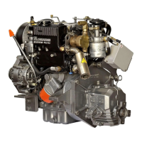
Radiator Cap: Inspect the vacuum valve (1) and the relief valve (2).
Fit the radiator cap onto a suitable radiator cap testing fixture.
Pressurize to 0.7 bar to insure the radiator cap holds rated pressure.
Replace the cap if 0.7 bar cannot be reached before pressure relief.
Replace the radiator cap if any degradation is seen on the vacuum
valve seal or the pressure relief seal or if the cap is bent, deformed or
damaged.
Radiator Seat: The sealing ability of the radiator cap is a function of
the radiator or expansion tank seat. Inspect the radiator cap seat and
replace/ repair as needed.
Cooling System Pressure Test: Fill the cooling system completely
with a 50/50% solution- water/ ethylene glycol. Fit a cooling system
pressurizing device to the cooling system fill port. Pressurize the
cooling system to 0.7 bar. The pressure should hold steady. If the
pressure does not hold steady at 0.7 bar, a malfunction in the
pressure device exists or a leak in the cooling system exists. Inspect
the cooling system for signs of liquid at all joints, hoses and at the
coolant pump. Tighten, repair or replace as required.
NOTE: Lombardini recommends a radiator cap pressure relief setting
of 0.7 bar. Do not operate the engine with a pressure cap of higher or
lower setting installed.
COOLANT PUMP DETAILS
The design of all LDW-FOCS coolant pumps is similiar. However, the
impeller(1) size and seal assembly (2) are larger for the LDW 1204
,LDW 1204/T and 1404, allowing for greater coolant flow.
Components:
1 Impeller
2 Seal assembly
3 Pump body
4 Weep hole
5 Bearing
6 Pulley
7 Shaft
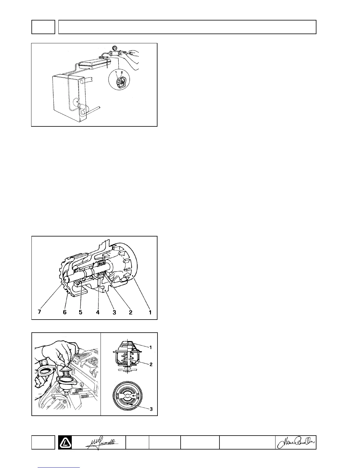
THERMOSTAT
Removal: Drain the engine coolant in a suitable container. Remove
the two(2) capcrews retaining the coolant outlet to the thermostat
housing. Remove the thermostat from the thermostat housing.
Inspection: Inspect the the thermostat for deposits, corrosion and
deformation. Clean or replace as required.
Components:
1 Thermostat body- stainless steel, brass or thermoplastic.
2 Expansion bulb
3 Bleed vent
NOTE: Metalic thermostats require a O-ring gasket- replace as
required.

 Loading...