WIRING MANUAL
The repair methods given by the manufacturer in this document are based on the technical specifications, current at the time of release. The methods may be modified as a result of changes introduced by the manufacturer in the production of the various component units and accessories from which the vehicles are manufactured. The reproduction,
translation, transmission, in part of or whole of the present document,are prohibited without the prior written consent of Mahindra & Mahindra Ltd. The use of this document by any person other than the trained personnel, at the Authorized Service Centre of Mahindra & Mahindra Ltd.,will amount to unauthorized use and shall be liable for penalty/
prosecution© 2013 Mahindra & Mahindra Ltd.
MAN-00233
MAY 2013/Rev1
25042013
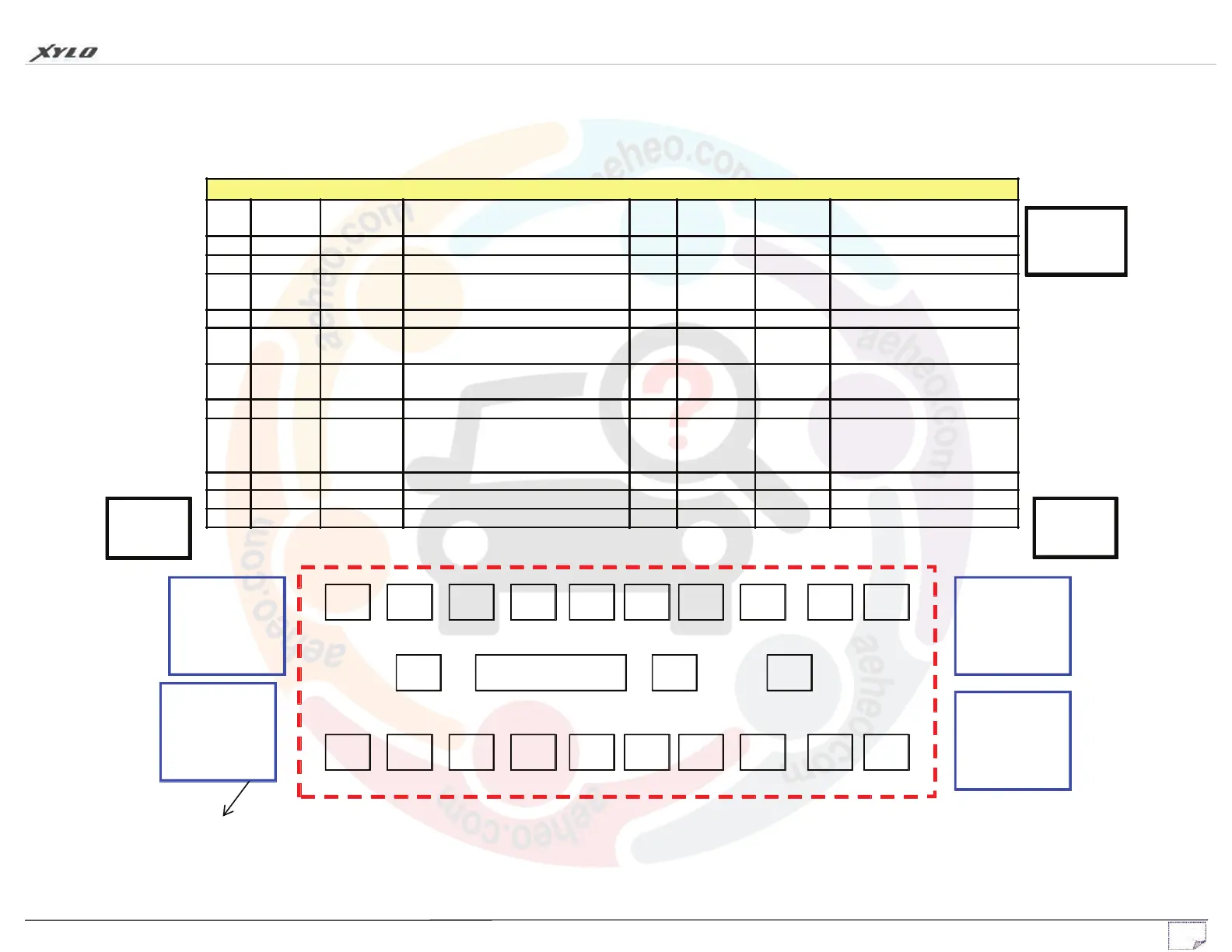
MAIN FUSE/RELAY BOX
LOCATION – RH SIDE OF INSTRUMENT PANEL (After opening driver door)
1
20A
PULLER
21
40A
2
30A
3
5A
4
10A
5
20A
6
10A
7
5A
8
15A
9
20A
10
5A
22
40A
20
5A
19
10A
18
10A
17
5A
16
10A
15
10A
14
7.5A
13
10A
12
15A
11
15A
PARK RELAY
20A
(BLACK)
DEMISTER
RELAY
20A
(BLACK)
DIS / IMMOBILISER/MVAC(H9)
OUTSIDE REAR VIEW
MIRROR/ FOG LAMP
MBFM/CENTRAL DOOR
LOCKING
C103
C378
C107
AC COMP
RELAY
20A
(BLACK DIODE)
REAR BLOWER
RELAY
20A
(BLACK)
APPLICABLE
FOR H9
MAIN FUSE / RELAY BOX
 Loading...