63
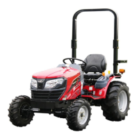
1. Main Spool Valve Bore
2. Relief Valve Bore
3. Plug Connecting Check Valve to Control Valve
4. Plug Connecting Cylinder to Control Valve
5. Lowering Port Connecting Control Valve Spring
chamber to Tank
6. Bypass Tank Port
7. Plug Connecting Pump, Relief Valve & Control Valve
8. Port Conecting Regulator Bore to reservor
9. Regulator Valve Bore
1
2
9
7
8
6
5
4
3
h. Position Control Valve Lift — Lower Test
Locate the position control stop at about
mid range.
Fully raise the lift arms then lower until the
control lever is against the stop.
Measure the height from the centre line of
the lower link ball ends to the ground.
Fully lower the lift arms then raise until the
control lever is against the stop and on the
same side of the stop as in the first test.
Measure the height of the ball ends from
the ground. If these two measurements
differ by more than 25.4mm. The control
valve spool may sticky.
i. Noise
There should be no noise from any part of
the hydraulic system apart from a slight hiss
caused by oil flow.
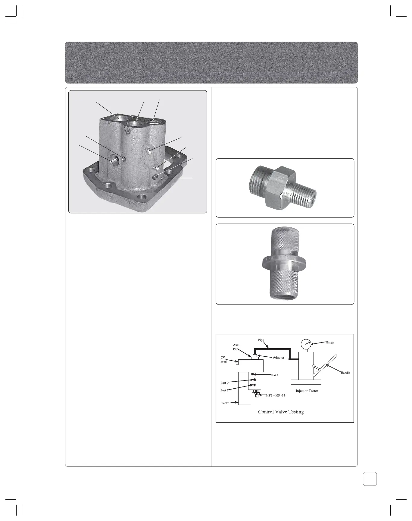
j. Pressure Testing the Valve Unit Before
Assembling to the Housing
a. Clean the control valve with help of air &
make it dry.
b. Remove external jack tapping plug. Fit
special tool MST-H1/2-HD-12 & MST-H1/2-
HD-11
c. Connect the hand pump (injecter tester) to
the external jack tapping.
d. Screw in the isolator valve.
e. Hole the spool at the full lift position
(inside).
Hy-tec Hydraulics
 Loading...